


ID-36TXN 054 50.01
ID-36 Operator Panel, Resistive TFT Panel 10 ", Panel Type
| DI | |
|---|---|
| DI/AI | |
| DO | |
| AI | |
| AO | |
| COM | 1x ETH 1x RS-485 |
| SENSOR |
| Picture | Variant | Variant description |
|---|---|---|

|
ID-36 |
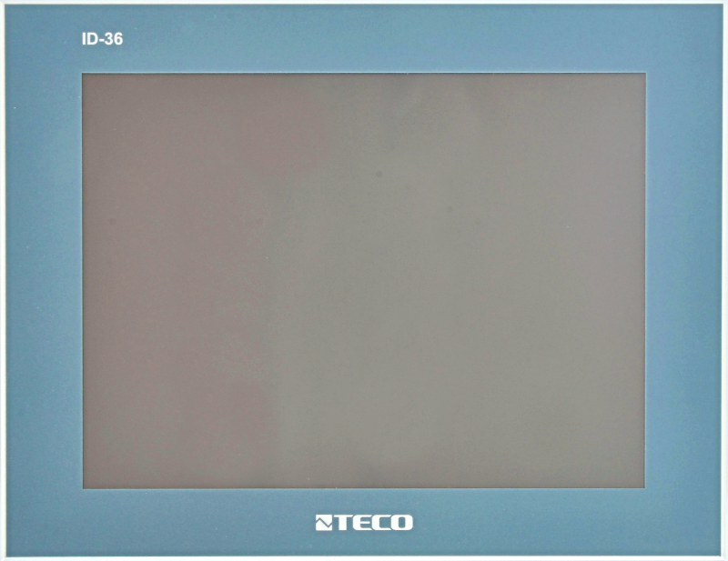
ID-36 The operator panel is intended for cooperation with TECOMAT TC700, TC800 and Foxtrot systems. User screens are created in the Mosaic programming environment by the WebMaker tool and are identical to the pages that are available in Tecomat via the web server.
The panel has a backlit resistive touch LCD TFT 10" display with a resolution of 800x600 points. It is powered by an external 24 V DC source. Communication between the control system and the ID-3x panel takes place via an Ethernet 100Base-TX interface or via a serial line with an RS-485 protocol interface EPSNET or TCL2 protocol.
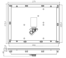
The ID-36 panel is designed for built-in installation.
The panel has a backlit resistive touch LCD TFT 10" display with a resolution of 800x600 points. It is powered by an external 24 V DC source. Communication between the control system and the ID-3x panel takes place via an Ethernet 100Base-TX interface or via a serial line with an RS-485 protocol interface EPSNET or TCL2 protocol.
The ID-36 panel is designed for built-in installation.
| Order num. | TXN 054 50.01 |
|---|---|
| Teco code | TXN 054 50.01 |
| Categories | HMI - Graphic touch panels |
| Tags | Sales and production discontinued |
| COM - Communication - IP/Ethernet | |
|---|---|
| Ethernet 10/100 Mb (ETHx) | 1 |
| Display parameters | |
| Characteristics | Color TFT LCD |
| Diagonal | 10,4" |
| Resolution | 800 x 600 pixels |
| Number of colors | 256k |
| Backlight | LED |
| Backlight lifetime | type. 20,000 hours |
| Touch panel | Resistive |
| Power supply | |
| Nominal supply voltage (V) | 24 V DC |
| Typical power input | 7 W |
| Galvanic separation of power supply from internal circuits | No |
| Internal protection | No |
| Size and weight | |
| Weight approx. | 450 g |
| Product dimensions (width x height x depth) | 275 x 216 mm |
| Operating conditions, product standards | |
| Product standard | ČSN EN 61131-2: 2005 (idt IEC61131-2: 2003) - Programmable control units |
| Protection class of electrical object | III, according to ČSN EN 61140 ed.3: 2016 (idt IEC 61140:2016) |
| IP rating (Ingress Protection) according to ČSN EN 60529: 1993 (idt IEC 529: 1989) | IP54 - front panel, IP20 - entire product |
| Operating areas | Normal, acc. ČSN 33 2000-1 ed.2: 2009 (mod IEC 60354-1:2005) |
| Degree of pollution | 2, according to ČSN EN 60664-1 ed.2: 2008 (idt IEC 60664-1: 2007) |
| Overvoltage category installation | II according to ČSN 33 0420-1 |
| Type of device | To the panel |
| Working position | Vertical |
| Type of operation (operating frequency) | Continuous |
| Ambient operating temperatures | -20 °C to + 55 °C |
| Operating relative humidity | from 10 % up to 95 % without condensation |
| Operating atmospheric pressure | min. 70 kPa (<3,000 m above sea level) |
| Storage temperatures | –25 °C to +70 °C |
| Storage environment | Dry, clean areas without conductive dust, aggressive gases or acid vapors for a period not exceeding the warranty period. |
| Transport temperatures | -25°C to -70°C |
| Transport environment | Covered means of transport, transport packaging must not be exposed to the effects of rain and snow |
| Electromagnetic compatibility, Mechanical endurance | |
| Electromagnetic compatibility / Emission | A, according to EN 55022: 1999 (mod CISPR22: 1997) |
| Emmisions - note | In premises where the use of radio and television receivers can be expected to be used a distance of 10 m from these devices may cause radio interference. In such a case, the user may be required to take appropriate action. |
| Electromagnetic compatibility / Immunity | min. as required by EN 61131-2: 2007 |
| Sinusoidal vibration endurance | 10 Hz to 57 Hz amplitude 0.075 mm, 57 Hz to 150 Hz acceleration 1 G, according to Fc according to ČSN EN 60068-2-6 ed.2:2008 (idt IEC 60068-2-6:2007), 10 cycles in each axis . |
| Packaginng, transportation, storage | |
| Description | The module is packed in a paper box. This documentation is also part of the package. The outer packaging is carried out according to the scope of the order and the method of transport in a transport package provided with labels and other data necessary for transport. The product must not be exposed to direct weather conditions during transport and storage. Malting of the product is only allowed in clean rooms without conductive dust, aggressive gases and vapors. The most suitable storage temperature is 20 ° C |
| Installation | |
| Assembly description |
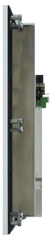
The ID-36 panel is intended for built-in installation, the front panel is made of aluminum. It's from behind panel protected only by a cover plate with IP20 protection. Ten metal ones are used for attachment clip with the fixing screws that are part of it. The mounting hole should have dimensions 264x205 mm. Operator panels must not be exposed to direct sunlight. |
| Connection | |
| Connection description |
The supply voltage of the 24 V DC source is connected to the removable terminal block on the +24 V terminals and GND, the GND terminal is not galvanically separated from the metal parts of the panel. The clamp is constructed for screw connection of conductors with a cross-section from 0.5 to 1.5 mm2. It is output on the same terminal block even RS-485 interface (terminals TxRx+ and TxRx-), EPSNET or TCL2 mode is set by software in the panel configuration dialog. In the Mosaic environment, the appropriate channel mode must be set RS-485 (PC for EPSNET protocol) or add a panel in the I/O configurator on the TCL2 bus. The terminals marked CIB+ and CIB- are prepared for the CIB interface, in the current HW version of the panel are not used. Alternatively, the panel can be powered via the Ethernet interface cable, when the supply voltage is 24 V connects to unused pairs 4/5 and 7/8, the polarity does not matter in this case. Appropriate passive power injection modules can commonly be purchased at computer hardware stores (often marked as a PoE module, even though it is not a Power over Ethernet standard). The ETHERNET interface is connected to a standard 8-pin RJ 45 socket performed with commonly available cables |
| Connection via connectors | Removable terminal block with screw terminal, wire max. 1.5 mm2 |
| Ethernet | RJ-45 |
| Module operation | |
| Module configuration |
After switching on, the default page will appear on the display. If communication is established with the PLC a The PLC is in RUN mode, the panel will automatically start uploading user definitions from the PLC screens and goes into RUN mode. When the PLC is in HALT or unavailable, it remains the default page with the inscription "HALT" or "Connecting to PLC..." is displayed on the panel. Because the panel communicates with the PLC protocol EPSNET, it is not listed in the HW configuration of the PLC and its disconnection does not affect the state of the PLC. The "Setup" button is located in the lower right corner of the default page. Pressing this button se brings up a dialog for setting parameters, such as the type of connection to the PLC, IP address of the PLC, IP panel address, time to turn off the display, default skin theme and more. It's here too the size of the project files stored in the panel is displayed. If due to frequent alternating projects, the space has been exhausted (approx. 28MB of data can be stored in the ID-3x) or it would be reduced file search speed, it is possible to delete these files with the "Clear" button (files project, which the panel needs for its operation, it will automatically download from the PLC again). Saving parameters is done with the "Save" button. If parameters need to be changed in RUN mode, the configuration dialog can be called up by clicking first to the upper left and then to the lower right corner of the display. It is also possible to connect to the panel using a web browser on port 8080. If the panel has set IP address, e.g. 192.168.134.178, just enter the address in the web browser in of the form http://192.168.134.178:8080 and the web browser will display the panel's configuration pages. You can there you can set similar parameters as after pressing the "Setup" button directly on the panel, but there is more here is a page that serves to upgrade the firmware of the panel or display debugs information |
| Maintenance | |
| Description | The module does not require any maintenance under general installation conditions. The operations in which a part of the module has to be dismantled must always be carried out with the supply voltage disconnected. |
| Instructions |
Do not use chemicals such as acetone, toluene, ethanol, isopropyl alcohol to clean the device etc. Remove dust inside the device with a stream of air or suction. Bezel and front panel clean with a soft cloth soaked in diluted detergent. For cleaning dusty or a dirty display touch panel, use a dry, soft cloth, such as a cloth for cleaning glasses. Remove dirt carefully to avoid scratching the surface layer. |
| Notice | Because the module contains semiconductor components, it is necessary to follow the principles for working with electrostatic sensitive components when handling the removed cover. It is not allowed to directly touch the printed circuit boards without protective measures !!! |
| Warranty | |
| Generally | Warranty and complaint conditions are governed by the Terms and Conditions of Teco a.s. |
| Notice | You must meet all the conditions of this documentation before turning on the system. The system must not be put into service unless it has been verified and confirmed that the machinery meets the requirements of Directive 89/392 / EEC, in so far as it applies to it. Documentation subject to change. |
HW documentation
ID-36 - Basic documentation
167.08 kB
ID-36 - basic documentation en
1.72 MB, (EN)
Firmware
Firmware ID-36 - change history
22.66 kB
Files for designers
Foxtrot 2 - library of elements in DXF and DWG formats, v. 2025/08.
21.80 MB
Foxtrot 2 - element library for SchemataCAD, v. 2025/08.
6.96 MB
- Graphic panels with a 10" display, the ID-36 - The operators panel ID-36 is designed for cooperation with TECOMAT TC700 systems and Foxtrot. User screens are created in the Mosaic programming environment with the Webmaker tool, and are therefore identical with the sites accessible via the web...
- Graphic panels with 4.3“ display, ID-31, ID-32 - ...tening the screws. Fig. 1. Wiring the connectors and connecting the power supply to panels ID-32, ID-31 and ID-36. Fig. 2. Mechanical dimensions and placement of the ID-32 module connectors Notes:...
- The operator panels - Several types of operator panels are available for Foxtrot systems (partly also for TC700): ID-31/ID-32 ID-36 ID-14 ID-16
No data available.