


PW-8901TXN 189 01
PW-8901; VM and VIO bus power source from 24 V DC
| DI | |
|---|---|
| DI/AI | |
| DO | |
| AI | |
| AO | |
| COM | |
| SENSOR |
| Picture | Variant | Variant description |
|---|---|---|

|
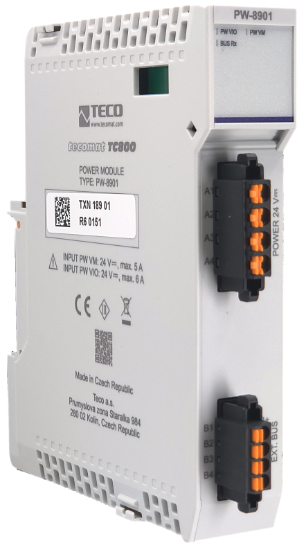
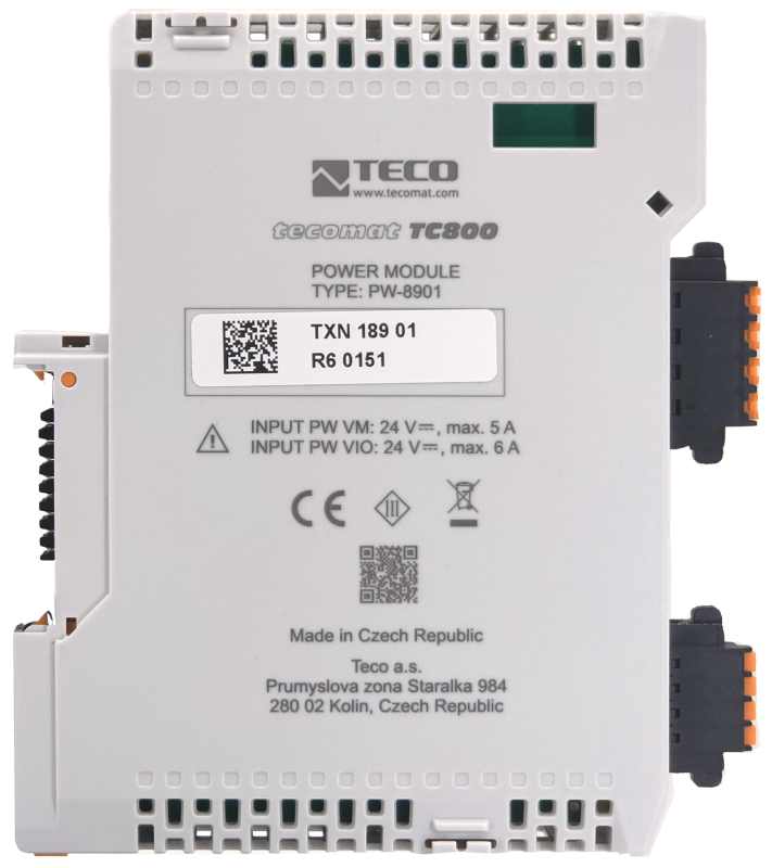
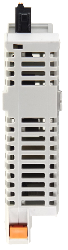
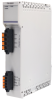
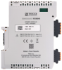
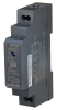
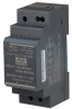
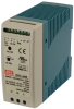
PW-8901 |
The PW-8901 is a power supply module in a 24 mm wide housing that generates two power supply voltages on the TC800 system bus from the 24 V DC network: VM for powering the internal circuits of the modules and VIO for powering the input circuits of selected modules. At the same time, it enables the connection of multiple frames via the TCL3 system bus. The connectors are screwless.
| Order num. | TXN 189 01 |
|---|---|
| Teco code | TXN 189 01 |
| Categories | TC800 - Power supply modules |
| Tags | - |
| Power supply | |
|---|---|
| Nominal supply voltage (V) | 24 V DC |
| Supply voltage, tolerances | 20 - 30 V DC |
| Maximum input current Ivm | 5 A |
| Maximum input current Ivio | 5 A |
| Module thermal/power loss | 1 W |
| Bridging a power failure | 10 ms min. |
| Integrated UPS function | No |
| Isolation voltage between VM, VIO and TCL3 | 500 V |
| Size and weight | |
| Weight approx. | 105 g |
| Product dimensions (width x height x depth) | 24 x 118 x 97 mm |
| Operating conditions, product standards | |
| Product standard | ČSN EN 61131-2:2008 (idt IEC 61131-2:2007) - Programmable control units |
| Protection class of electrical object | III, according to ČSN EN 61140 ed.3: 2016 (idt IEC 61140:2016) |
| IP rating (Ingress Protection) according to ČSN EN 60529: 1993 (idt IEC 529: 1989) | IP20 |
| Operating areas | Normal, acc. ČSN 33 2000-1 ed.2: 2009 (mod IEC 60354-1:2005) |
| Degree of pollution | 2, according to ČSN EN 60664-1 ed.2: 2008 (idt IEC 60664-1: 2007) |
| Overvoltage category installation | II, according to EN 60664-1 ed_2: 2008 (idt IEC 60641-1: 2007) |
| Type of device | Built-in |
| Working position | Vertical |
| Type of operation (operating frequency) | Continuous |
| Ambient operating temperatures | -20 °C to + 55 °C |
| Operating relative humidity | from 10 % up to 95 % without condensation |
| Operating atmospheric pressure | min. 70 kPa (<3,000 m above sea level) |
| Storage temperatures | –25 °C to +70 °C |
| Storage relative humidity | Max. 80% without vapor condensation |
| Storage environment | Dry, clean areas without conductive dust, aggressive gases or acid vapors for a period not exceeding the warranty period. |
| Transport temperatures | -25°C to -70°C |
| Transport environment | Covered means of transport, transport packaging must not be exposed to the effects of rain and snow |
| Electromagnetic compatibility, Mechanical endurance | |
| Electromagnetic compatibility / Emission | A, according to EN 55032 ed. 2: 2017 (idt CISPR 32: 2015) |
| Electromagnetic compatibility / Immunity | min. as required by EN 61131-2: 2007 |
| Sinusoidal vibration endurance | 10 Hz to 57 Hz amplitude 0.075 mm, 57 Hz to 150 Hz acceleration 1 G, according to Fc according to ČSN EN 60068-2-6 ed.2:2008 (idt IEC 60068-2-6:2007), 10 cycles in each axis . |
| Packaginng, transportation, storage | |
| Description | The module is packed in a paper box. This documentation is also part of the package. The outer packaging is carried out according to the scope of the order and the method of transport in a transport package provided with labels and other data necessary for transport. The product must not be exposed to direct weather conditions during transport and storage. Malting of the product is only allowed in clean rooms without conductive dust, aggressive gases and vapors. The most suitable storage temperature is 20 ° C |
| Installation | |
| Assembly description | The installation of the TC800 system module is carried out by sliding it perpendicularly onto the DIN rail ČSN EN 50022 with busbar and locking latch in the lower part of the module. A more detailed description and mechanical drawings with dimensions are given in the documentation TXV 004 72. |
| Connection | |
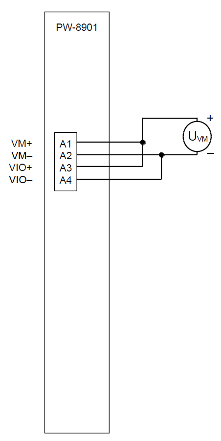
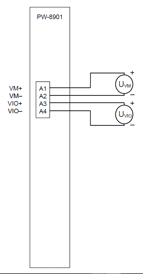
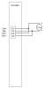
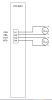
| Power connection | Connector with screwless terminals 0.2 ~ 1.5 mm2 |
| Connection description | An example of module connection is shown in the following figure. |
| Maintenance | |
| Description | The module does not require any maintenance under general installation conditions. The operations in which a part of the module has to be dismantled must always be carried out with the supply voltage disconnected. |
| Notice | Because the module contains semiconductor components, it is necessary to follow the principles for working with electrostatic sensitive components when handling the removed cover. It is not allowed to directly touch the printed circuit boards without protective measures !!! |
| Warranty | |
| Generally | Warranty and complaint conditions are governed by the Terms and Conditions of Teco a.s. |
| Notice | You must meet all the conditions of this documentation before turning on the system. The system must not be put into service unless it has been verified and confirmed that the machinery meets the requirements of Directive 89/392 / EEC, in so far as it applies to it. Documentation subject to change. |
HW documentation
PW-8901 - basic documentation (en)
1.45 MB, (EN)
Files for designers
TC800 - library of elements in DXF and DWG formats, v. 2025/01
493.14 kB
TC800 - element library for SchemataCAD, v. 2025/01
130.34 kB
EC - Declaration of Conformity
TC800 - CE declaration of conformity (cs)
292.20 kB
TC800 - CE Declaration of Conformity (en)
709.29 kB
- Power supply modules PW-8901 and PW-8902 - The PW-8901 power supply module is designed to power TECOMAT TC800 PLC assemblies from a 24 V DC network in a 24 mm wide case. It is a module that provides power for internal circuits (VM) and IO circuits (VIO) with an output level of 24 V SELV (c...
- TCL3, connecting multiple TC800 frames, fundamentals, connection example - ...nterface. The resulting system always has one central module (CP-8001), and each frame must contain one power supply module (PW-8901), which provides both power to the modules in the frame and the TCL3 bus connection between the frames. The follow...
- Handling Modules and Assembling the TC800 System - ...C800 System Configuration A typical TC800 system configuration consists, from left to right, of a power supply module (PW-8901), a base module (CP-8001), and peripheral modules. The modules are mounted on the system bus (in Fig. 1, this is an R...
- Examples of power connections for TC800 modules - ...s article describes the correct examples of powering the modules (both internal and IO circuits) of the TC800 system. The PW-8901 power supply module has two power level inputs VM and VIO on connector A. We connect the 24 VDC supply voltage to...
- TC800 power supply sizing calculation and heat loss - ...nbsp; PW-8901 TXN 189 01 2 0,8 W 0,1 W 3,2 W 1) 3,2 W 1)...
- TECOMAT TC800 SYSTEM FEATURES - ...rticle CENTRAL MODULES TC800 . Basic overview of TC800 modules Central module CP-8001 Power supply modules PW-8901 and PW-8902 Binary input module IB-8302 Binary input module IB-8310 Binary output module OS-8401...
No data available.