

C-WS-1202R-TG2-0DC-WS-1202R-TG2-0D
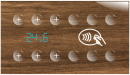
C-WS-1202R-TG2-0D; CIB, Touch control glass, 12 buttons, temperature and humidity sensor, 4xAI / DI, 2xDO, without display
| DI | max. 12 touch buttons according to configuration |
|---|---|
| DI/AI | max. 4x DI/AI |
| DO | max. 2x DO, according to configuration max. 12x signaling LED R/G/B, according to configuration |
| AI | |
| AO | |
| COM | 2x CIB slave |
| SENSOR | 1x Temperature 1x Moisture 1x CO2 - according to configuration 1x RFID - according to configuration |
| Picture | Variant | Variant description |
|---|---|---|

|
C-WS-1202R-TG2-0D | Number of buttons: 12 |

|
C-WS-1202R-TG2-1W | Number of buttons: 12 Number of displays: 1x white display |

|
C-WS-1202R-TG2-1B | Number of buttons: 12 Number of displays: 1x white display |

|
C-WS-0602R-TG2-0D-R | Number of buttons: 6 Sensor: RFID |

|
C-WS-0602R-TG2-1W-R | Number of buttons: 6 Number of displays: 1x white display Sensor: RFID |

|
C-WS-0602R-TG2-1B-R | Number of buttons: 6 Number of displays: 1x display blue Sensor: RFID |

|
C-WS-1202R-TG2-2W | Number of buttons: 12 |

|
C-WS-1202R-TG2-2B | Number of buttons: 12 |

|
C-WS-0602R-TG2-0D-C | Number of buttons: 6 Sensor: CO2 |

|
C-WS-0602R-TG2-1B-C | Number of buttons: 6 Number of displays: 1x display blue Sensor: CO2 |

|
C-WS-0602R-TG2-1W-C | Number of buttons: 6 Number of displays: 1x white display Sensor: CO2 |

|
C-WS-12P2R-TG2-0D | Number of buttons: 6 (with depressions) |

|
C-WS-12P2R-TG2-1B | Number of buttons: 6 (with depressions) Number of displays: 1x display blue |

|
C-WS-12P2R-TG2-1W | Number of buttons: 6 (with depressions) Number of displays: 1x white display |

|
C-WS-12P2R-TG2-2W | Number of buttons: 6 (with depressions) |

|
C-WS-12P2R-TG2-2B | Number of buttons: 6 (with depressions) |
C-WS-xxx2R-TG2-yy
Wall-mounted glass touch controller with two basic square modules with a final dimension of 165 x 94 mm for installation in multiple instrument boxes for combined frames with a pitch of 71 mm.
This double controller requires 2 addresses and 2 modules on the CIB bus.
It is delivered as a set with an individual configuration of each of the two modules, including a cover glass with individual printing of icons, texts and backgrounds. The web configurator at:
https://touchatglass.com/eng/configurator.html
The glass can also be ordered separately as a spare.
| Order num. | 8020104456 |
|---|---|
| Teco code | C-WS-1202R-TG2-0D |
| Categories | CFox - Touch@Glass, devices |
| Tags | - |
| COM - System buses | |
|---|---|
| CIB - Common Installation Bus (R): Installation I/O bus | 1x CIB slave |
| DI - Parameters of binary inputs DC (group A) | |
| Number of inputs in group | 2 |
| Common wire | GND - module ground |
| Combined input type | DI/AI Active, for sensing potential-free contacts and measuring resistance sensors |
| DO - Parameters of binary transistor outputs (group A) | |
| Number of transistor outputs | 1 |
| Output type | MOSFET (Low-side switch) |
| Switching voltage | 27 V DC |
| Switching current, output load | 3 A max. |
| Short-term output overload capacity | 3 A max. |
| AI - Organization of analog inputs | |
| Total number of analog inputs | 2 |
| Number of inputs per group | 1 |
| Number of analog input groups | 2 |
| Organization of analog inputs into groups | 1x AI/DI1, 1x AI/DI2 |
| Input type | AI / DI - combined |
| AI - Analog Input Ranges (Group A) | |
| Voltage | 0-2 V |
| Passive sensor | Pt1000, W100 = 1,385 (-90 to +320 °C) |
| Passive sensor | Pt1000, W100 = 1,391 (-90 to +320 °C) |
| Passive sensor | Ni1000, W100 = 1,500 (–60 to +200 ° C) |
| Passive sensor | Ni1000, W100 = 1.617 (-60 to +200 ° C) |
| Passive sensor | Resistance transmitter 0-100 kOhm |
| Passive sensor | KTY81-121; PTC thermistor (-55 to + 125 °C) |
| Passive sensor | NTC Thermistor 12k / 25 °C (-40 to + 125 °C) |
| Temperature measurement error | ± 1°C |
| Parameter des Temperatursensors | |
| Temperature - Measurement range | 0°C ÷ 50°C |
| Temperature - Measurement accuracy | typ. ±0,5 °C |
| Humidity sensor parameters | |
| Relative humidity - Measurement range | 0 ÷ 100 %RH |
| Relative humidity - Measurement accuracy | typ. ±2 %RH |
| Power supply | |
| Supply voltage, tolerances | 24 V DC, +25%, -15%, SELV |
| Maximum power input | 0,7 W |
| Power supply from CIB - typical current consumption (mA) | 28 mA |
| Power supply from CIB - Galvanic separation of power supply from internal circuits | No |
| Internal protection | No |
| Size and weight | |
| Weight approx. | 140 g |
| Product dimensions (width x height x depth) | 94 x 94 x 10 mm |
| Operating conditions, product standards | |
| Product standard | ČSN EN 60730-1 ed.4 :2017 (EN 60730-1:2016) -Automatic electronic control device (for household and similar purposes) |
| Protection class of electrical object | III, according to ČSN EN 61140 ed.3: 2016 (idt IEC 61140:2016) |
| IP rating (Ingress Protection) according to ČSN EN 60529: 1993 (idt IEC 529: 1989) | IP10B |
| Operating areas | Normal, acc. ČSN 33 2000-1 ed.2: 2009 (mod IEC 60354-1:2005) |
| Degree of pollution | 2, according to ČSN EN 60664-1 ed.2: 2008 (idt IEC 60664-1: 2007) |
| Overvoltage category installation | II, according to EN 60664-1 ed_2: 2008 (idt IEC 60641-1: 2007) |
| Type of device | Built-in |
| Working position | Vertical |
| Type of operation (operating frequency) | Continuous |
| Ambient operating temperatures | 0 ° C to + 55 ° C |
| Operating atmospheric pressure | min. 70 kPa (<3,000 m above sea level) |
| Storage temperatures | –25 ° C to + 85 ° C |
| Storage relative humidity | Max. 80% without vapor condensation |
| Electromagnetic compatibility, Mechanical endurance | |
| Electromagnetic compatibility / Emission | B, according to EN 55032 ed. 2: 2017 (idt CISPR 32: 2015) |
| Electromagnetic compatibility / Immunity | min. as required by EN 61131-2: 2007 |
| Sinusoidal vibration endurance | 10 Hz to 57 Hz amplitude 0.075 mm, 57 Hz to 150 Hz acceleration 1 G, according to Fc according to ČSN EN 60068-2-6 ed.2:2008 (idt IEC 60068-2-6:2007), 10 cycles in each axis . |
| Packaginng, transportation, storage | |
| Description | The module is packed in a paper box. This documentation is also part of the package. The outer packaging is carried out according to the scope of the order and the method of transport in a transport package provided with labels and other data necessary for transport. The product must not be exposed to direct weather conditions during transport and storage. Malting of the product is only allowed in clean rooms without conductive dust, aggressive gases and vapors. The most suitable storage temperature is 20 ° C |
| Installation | |
| Assembly description | The module is mounted in a vertical position on the U-rail ČSN EN 50022. Installation of the assembly (basic module and possibly peripheral modules) is performed according to TXV 004 13. |
| Assembly description |
1. screw the mounting frame to the installation box (pay attention to the orientation) 2. connect the electronics module to the other wiring 3. insert the electronics module into the installation box 4. snap the glass fingerboard onto the mounting frame |
| Connection | |
| Connection of power and system communication | connector with 1.5 mm2 screw terminal |
| Module operation | |
| Commissioning | The module is operated, set and diagnosed from the MOSAIC programming environment or other parameterization software. The module is ready for operation after connecting the supply voltage and the CIB bus. The HW address is indicated on the label on the module. |
| Module diagnostics | The basic diagnostics is performed internally and the result is available in the relevant registers of the Mosaic environment. |
| Maintenance | |
| Description | The module does not require any maintenance under general installation conditions. |
| Warranty | |
| Generally | Warranty and complaint conditions are governed by the Terms and Conditions of Teco a.s. |
| Notice | You must meet all the conditions of this documentation before turning on the system. The system must not be put into service unless it has been verified and confirmed that the machinery meets the requirements of Directive 89/392 / EEC, in so far as it applies to it. Documentation subject to change. |
No data available.

TOUCH-120M, Replacement glass
TOUCH-120M
TOUCH-120M; Cover glass Touch@Glass optional; 2 Modules, 94x165 mm without recesses, assembly kit with plastic and magnet
TOUCH-12PM
TOUCH-12PM
TOUCH-12PM; Cover glass Touch@Glass optional; 2 Modules, 94x165mm with recesses, mounting kit with plastic and magnet
No data available.
No data available.