
C-RC-0003R-Decente, titaniumTXN 133 37.OD33
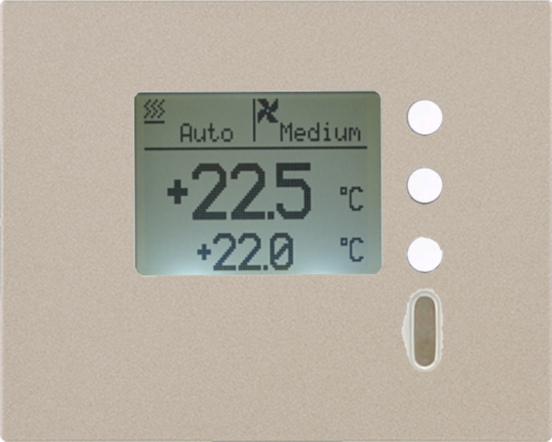
C-RC-0003R-Decente, titanium; CIB, Wall controller with LCD-HL1, 3 buttons, temperature and humidity sensor
| DI | 3x Button |
|---|---|
| DI/AI | 1x DI/AI |
| DO | |
| AI | |
| AO | |
| COM | 1x LCD graphic 98x64px |
| SENSOR | 1x Temperature 1x Humidity |
| Picture | Variant | Variant description |
|---|---|---|

|
C-RC-0003R-Decente, snow white | Color: Snow white |

|
C-RC-0003R-Decente, anthracite black | Color: Anthracite black |

|
C-RC-0003R-Decente, aluminum | Color: Aluminum |

|
C-RC-0003R-Decente, graphite | Color: Graphit |

|
C-RC-0003R-Decente, gold | Color: Gold |

|
C-RC-0003R-Decente, titanium | Color: Titanium |

|
C-RC-0003R-Decente, black matt | Color: Black matt |

|
C-RC-0003R-Decente, white matt | Color: White matt |
C-RC-0003R-Decente, snow white; CIB, Wall controller with LCD-HL1, 3 buttons, temperature and humidity sensor;
| Order num. | TXN 133 37.OD33 |
|---|---|
| Teco code | TXN 133 37.OD33 |
| Categories | CFox - DECENTE, Covers and devices |
| Tags | Temporarily unavailable |
| COM - System buses | |
|---|---|
| CIB - Common Installation Bus (R): Installation I/O bus | 1x CIB slave |
| AI - Analog Input Ranges (Group A) | |
| Parameters valid for inputs on the terminals | DI/AI1 |
| Passive sensor | Pt1000, W100 = 1,385 (-90 to +320 °C) |
| Passive sensor | Pt1000, W100 = 1,391 (-90 to +320 °C) |
| Passive sensor | Ni1000, W100 = 1,500 (–60 to +200 ° C) |
| Passive sensor | Ni1000, W100 = 1.617 (-60 to +200 ° C) |
| Passive sensor | Resistance transmitter 0-160 kOhm |
| Passive sensor | KTY81-121; PTC thermistor (-55 to + 125 °C) |
| Passive sensor | NTC Thermistor 12k / 25 °C (-40 to + 125 °C) |
| DI: Voltage-free contact | 0 when> 1.5 kOhm, 1 when <0.5 kOhm |
| DI: Balanced resistance input | 2x 1k1 (tamper/0/1/tamper) |
| Resistance measurement error - maximum error at 25 ° C | ± 0.5% of full scale |
| Power supply | |
| Supply voltage, tolerances | 24/27 V DC from CIB bus |
| Power supply from CIB - typical current consumption (mA) | 10 mA |
| Power supply from CIB - maximum current consumption (mA) | 17 mA |
| Internal protection | No |
| Size and weight | |
| Weight approx. | 75 g |
| Product dimensions (width x height x depth) | 86 × 86 × 35 mm |
| Operating conditions, product standards | |
| Product standard | ČSN EN 60730-1 ed. 2:2001 (mod IEC 60730-1:1999) |
| Protection class of electrical object | III, according to ČSN EN 61140 ed.3: 2016 (idt IEC 61140:2016) |
| IP rating (Ingress Protection) according to ČSN EN 60529: 1993 (idt IEC 529: 1989) | IP20 |
| Operating areas | Normal, acc. ČSN 33 2000-1 ed.2: 2009 (mod IEC 60354-1:2005) |
| Degree of pollution | 1, according to ČSN EN 60664-1 ed.2:2008 ( idt IEC 60664-1:2007) |
| Overvoltage category installation | II, according to EN 60664-1 ed_2: 2008 (idt IEC 60641-1: 2007) |
| Type of device | In the installation box on the wall |
| Working position | Any |
| Type of operation (operating frequency) | Continuous |
| Ambient operating temperatures | 0 ° C to + 55 ° C |
| Operating relative humidity | from 10 % up to 95 % without condensation |
| Operating atmospheric pressure | min. 70 kPa (<3,000 m above sea level) |
| Storage temperatures | –25 °C to +70 °C |
| Electromagnetic compatibility, Mechanical endurance | |
| Electromagnetic compatibility / Emission | B, according to EN 55032 ed. 2: 2017 (idt CISPR 32: 2015) |
| Electromagnetic compatibility / Immunity | min. according to ČSN EN 60730-1 ed.2: 2001 |
| Sinusoidal vibration endurance | 10 Hz to 57 Hz, amplitude 0,075 mm, 57 Hz to 150 Hz, acceleration 1 G (Fc test according to EN 60068-2-6: 1997 (idt IEC 68-2-6: 1995), 10 cycles per axis.) |
| Connection | |
| Connection description | An example of module connection is shown in the following figure. |
| Connection of inputs / outputs | terminal block with spring clamp 0.15-0.5 mm2, push-in |
| Module operation | |
| Module configuration |
The module is operated, set and diagnosed from the programming MOSAIC. For more information, see the Bus Peripherals module CIB TXV 004 13. |
| Module diagnostics | The basic diagnostics is performed internally and the result is available in the relevant registers of the Mosaic environment. |
| Maintenance | |
| Description | The module does not require any maintenance under general installation conditions. The operations in which a part of the module has to be dismantled must always be carried out with the supply voltage disconnected. |
| Notice | Because the module contains semiconductor components, it is necessary to follow the principles for working with electrostatic sensitive components when handling the removed cover. It is not allowed to directly touch the printed circuit boards without protective measures !!! |
| Warranty | |
| Generally | Warranty and complaint conditions are governed by the Terms and Conditions of Teco a.s. |
| Notice | You must meet all the conditions of this documentation before turning on the system. The system must not be put into service unless it has been verified and confirmed that the machinery meets the requirements of Directive 89/392 / EEC, in so far as it applies to it. Documentation subject to change. |
HW documentation
C-RC-0003R_U01 Basic Documentation
113.29 kB
Files for designers
Foxtrot 2 - library of elements in DXF and DWG formats, v. 2025/08.
21.80 MB
Foxtrot 2 - element library for SchemataCAD, v. 2025/08.
6.96 MB
No data available.
No data available.