


C-EM-0401M-STXN 133 22.90
C-EM-0401M-S; CIB fast electricity meter / quality meter, power supply 230 V AC / DC, 4x U, 4x I - current transformer x: 100 mA, 1x RO
| DI | |
|---|---|
| DI/AI | |
| DO | 1x RO |
| AI | 4x U (230 V AC) 4x I (100mA AC) |
| AO | |
| COM | 1x CIB slave |
| SENSOR |
| Picture | Variant | Variant description |
|---|---|---|

|
C-EM-0401M-S |
C-EM-0401M; CIB fast electricity meter / quality meter, power supply 230 V AC / DC, 4x U, 4x I - current transformer x: 100 mA, 1x RO
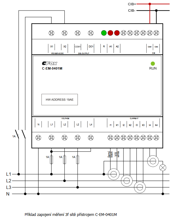
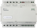
The C-EM-0401M-P035 module is a fast 4-quadrant electricity meter / quality meter providing all parameters of the consumed and supplied energy every 200 ms for four phases. It can be used for one three-phase and one single-phase measurement at the same time as well as for four separate single-phase measurements. The measurement is indirect, currents are sensed by current transformers with a unified 100 mA output. Current transformers are not part of the delivery and must be ordered separately according to the required current range from 50 A up to 2400 A .. The module has one relay output controlled by the implemented voltage and frequency protection function. The range of monitored voltage and frequency, including reaction times and recovery time after the cause of protection activation has disappeared, can be set parametrically from the application program in the basic module.
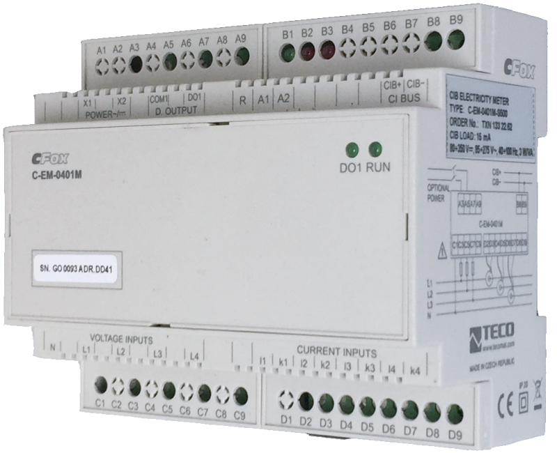
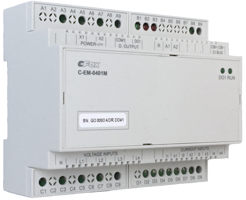
The module is designed for a DIN rail switchboard. It is connected to the Foxtrot basic module via a two-wire CIB Common Installation Bus®.
The C-EM-0401M-P035 module is a fast 4-quadrant electricity meter / quality meter providing all parameters of the consumed and supplied energy every 200 ms for four phases. It can be used for one three-phase and one single-phase measurement at the same time as well as for four separate single-phase measurements. The measurement is indirect, currents are sensed by current transformers with a unified 100 mA output. Current transformers are not part of the delivery and must be ordered separately according to the required current range from 50 A up to 2400 A .. The module has one relay output controlled by the implemented voltage and frequency protection function. The range of monitored voltage and frequency, including reaction times and recovery time after the cause of protection activation has disappeared, can be set parametrically from the application program in the basic module.
The module is designed for a DIN rail switchboard. It is connected to the Foxtrot basic module via a two-wire CIB Common Installation Bus®.
| Order num. | TXN 133 22.90 |
|---|---|
| Teco code | TXN 133 22.90 |
| Categories | CFox - Modules on DIN rail |
| Tags | Sales and production discontinued |
| COM - System buses | |
|---|---|
| CIB - Common Installation Bus (R): Installation I/O bus | 1x CIB slave |
| RO - Parameters of binary relay outputs (group A) | |
| Number of relay outputs | 1 |
| Switching current | 2 A max., 100 mA min. |
| Switching voltage | 250 V AC max., 5 V AC min., 30V DC max. |
| Measurement of supply network parameters - frequency | |
| Nominal frequency | 50/60 Hz |
| Frequency range | 42÷57 Hz/51÷70 Hz |
| Frequency measurement accuracy | ±20 mHz |
| Accuracy of current asymmetry measurement | ± 1% of value or ± 0.5 |
| Measurement of supply network parameters - voltage | |
| Measuring range, phase voltage (UL-N) | 6÷300 V AC |
| Measuring range, combined voltage (UL-L) | 11÷520 V AC |
| Voltage measurement accuracy | ± 0.05% of value or ± 0.02% of range |
| Input impedance | min. 2,7 MΩ |
| Input consumption | max. 0,03 VA |
| Permanent overload (UL-N) | 1300 V AC |
| Peak overload, for 1 s (UL-N) | 1950 V AC |
| Voltage asymmetry, measuring range | 0÷10 % |
| Accuracy of voltage asymmetry measurement | ± 0.3% of value or ± 0.3 |
| Total harmonic distortion voltage (THDU), measuring range | 0÷20 % |
| Harmonic voltage, measuring range, class 3 according to IEC 61000-2-4 ed. 2 | 10÷100 % |
| Accuracy of harmonic voltage measurement | twice the levels of class II according to IEC 61000-4-7 ed. 2 |
| Measurement of supply network parameters - currents | |
| Method for measuring current | indirect via current transformer |
| Measuring range | 0,0025÷1,2×Inom |
| Current measurement accuracy | ± 0.05% of value or ± 0.02% of range |
| Input impedance | 0,7÷91 Ω |
| Input consumption | max. 0,05 VA |
| Permanent overload | 2×Inom |
| Peak overload, for 1 s, repetition period min. 300 s |
INOM<35 A: 20×INOM INOM=35÷100 A: 10×INOM INOM>100 A: 5×INOM |
| Current asymmetry, measuring range | 0÷100 % |
| Total harmonic current distortion (THDI), measuring range | 0÷200 % |
| THDI measurement accuracy | THDI≤100%: ± 0.6; THDI> 100%: ± 0.6 of value |
| Harmonic / interharmonic current, measuring range (up to order 50) | 0 ÷ 500% class 3 according to IEC 61000-2-4 ed. 2 |
| Harmonic current measurement accuracy | IH≤10% INOM: ± 1% INOM; IH> 10% INOM: ± 1% of value |
| Measurement of supply network parameters - other quantities | |
| Active power, measuring range (PNOM = UNOM × INOM×cosφ); [W, V, A] | limited by measured voltage and current ranges |
| Reactive power, measuring range (QNOM = UNOM × INOM×sinφ); [VA, V, A] | limited by measured voltage and current ranges |
| Accuracy of active or reactive power (A) | ± 0.5% of value or ± 0.005% of range |
| Energy, measuring range | four-quadrant resp. six-quadrant; limited by measured voltage and current ranges |
| Accuracy of active energy measurement | class 1 (according to EN 62053-21) |
| Accuracy of reactive energy measurement | class 2 (according to EN 62053-23) |
| Power factor measurement accuracy (cos φ) | ±0,005 |
| Power supply | |
| Auxiliary power supply - voltage | 85÷275 V AC, 80÷350 V DC |
| Typical power input | 3 W |
| Module thermal/power loss | 4 W |
| Galvanic separation of power supply from internal circuits | No |
| Internal protection | Yes, PTC reversible fuse |
| Size and weight | |
| Weight approx. | 200 g |
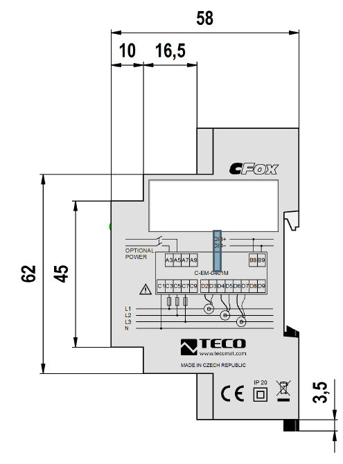
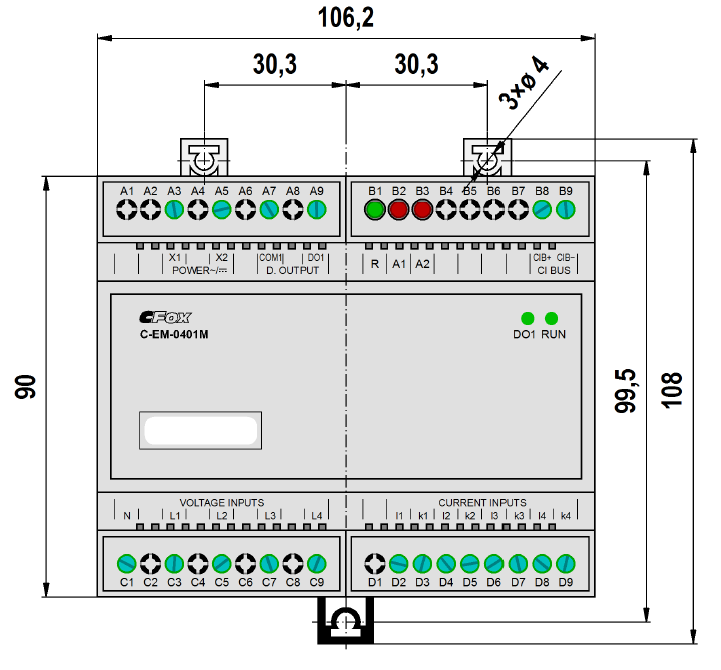
| Product dimensions (width x height x depth) | 105 x 92 x 58 mm |
| Module width in multiples of M (17.5 mm) | 6M |
| Operating conditions, product standards | |
| Product standard | ČSN EN 60730-1 ed. 3:2012 (mod IEC 60730-1:2010) |
| Protection class of electrical object | II, according to ČSN EN 61140 ed.3: 2016 (idt IEC 61140:2016) |
| IP rating (Ingress Protection) according to ČSN EN 60529: 1993 (idt IEC 529: 1989) | IP20 |
| Operating areas | Normal, acc. ČSN 33 2000-1 ed.2: 2009 (mod IEC 60354-1:2005) |
| Degree of pollution | 2, according to ČSN EN 60664-1 ed.2: 2008 (idt IEC 60664-1: 2007) |
| Overvoltage category installation | III, according to EN 60664-1 ed_2: 2008 (idt IEC 60641-1: 2007) |
| Type of device | Module on DIN rail |
| Working position | Vertical |
| Type of operation (operating frequency) | Continuous |
| Ambient operating temperatures | -20 °C to + 55 °C |
| Operating relative humidity | from 10 % up to 95 % without condensation |
| Operating atmospheric pressure | min. 70 kPa (<3,000 m above sea level) |
| Storage temperatures | –25 °C to +70 °C |
| Electromagnetic compatibility, Mechanical endurance | |
| Electromagnetic compatibility / Emission | A, according to EN 55032 ed. 2: 2017 (idt CISPR 32: 2015) |
| Electromagnetic compatibility / Immunity | min. according to ČSN EN 60730-1 ed.3: 2012 |
| Sinusoidal vibration endurance | 10 Hz to 57 Hz, amplitude 0,075 mm, 57 Hz to 150 Hz, acceleration 1 G (Fc test according to EN 60068-2-6: 1997 (idt IEC 68-2-6: 1995), 10 cycles per axis.) |
| Packaginng, transportation, storage | |
| Description | The module is packed in a paper box. This documentation is also part of the package. The outer packaging is carried out according to the scope of the order and the method of transport in a transport package provided with labels and other data necessary for transport. The product must not be exposed to direct weather conditions during transport and storage. Malting of the product is only allowed in clean rooms without conductive dust, aggressive gases and vapors. The most suitable storage temperature is 20 ° C |
| Installation | |
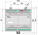
| Assembly description | The module can be mounted in two ways: either by mounting it on the instrument support U rail 35 mm wide ČSN EN 60715, or by screwing three screws to the base (after pulling out the three fastening clips located on the bottom of the module, max. Screw diameter is 4 mm). The dimensions of the module and the spacing of the holes for mounting the module on the screws are shown in Fig. 1. Natural air circulation must be allowed at the place of installation of the device and its immediate surroundings. More information on installation can be found in the CFox, RFox and Foxtrot Design Guide, order no .: TXV 004 16. |
| Connection | |
| Connection of power and system communication | terminal block with screw terminal 2.5 mm2 |
| Connection of inputs / outputs | terminal block with screw terminal 1.5 mm2 |
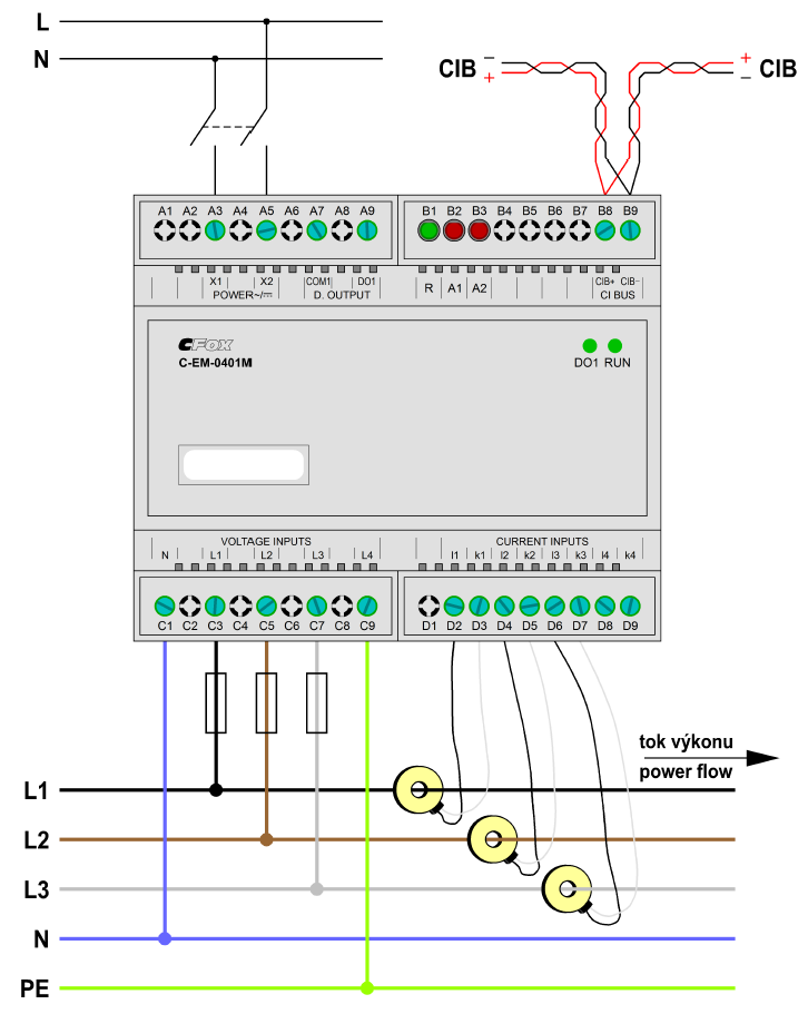
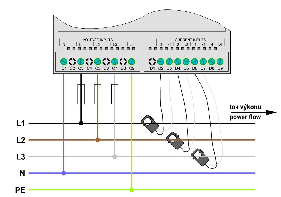
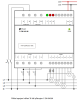
| Connection description | An example of module connection is shown in the following figure. |
| Module operation | |
| Commissioning |
The module is ready for operation after connecting the auxiliary supply voltage and the CIB bus. It contains no controls and is operated, set up and diagnosed from the MOSAIC or FoxTool programming environment. The HW address is indicated on the label on the front panel. For TXN 133 22.90 to .92 module variants, the correct primary current value of the respective current transformers (current range) must be entered during their initialization. Notice: CIB master CF-1140 / CF-1141 with FW version 2.0 and higher is required for correct operation of the module! Attention: When working with the module, it is necessary to observe all necessary measures for the protection of persons and property against injury and damage by electric shock! The module must be operated by a person with the prescribed qualification for such an activity and this person must be thoroughly acquainted with the principles of working with the module. If the module is connected to parts that are under dangerous voltage, it is necessary to observe all necessary measures to protect users and equipment from electric shock. Workers installing and / or maintaining the equipment must be equipped and use personal protective equipment and other safety equipment at work. If the module is used in a manner not specified by the manufacturer, the protection provided by the module may be reduced. Further information can be found in the manual Peripheral modules on the CIB bus, order no .: TXV 004 13.01. |
| Module diagnostics |
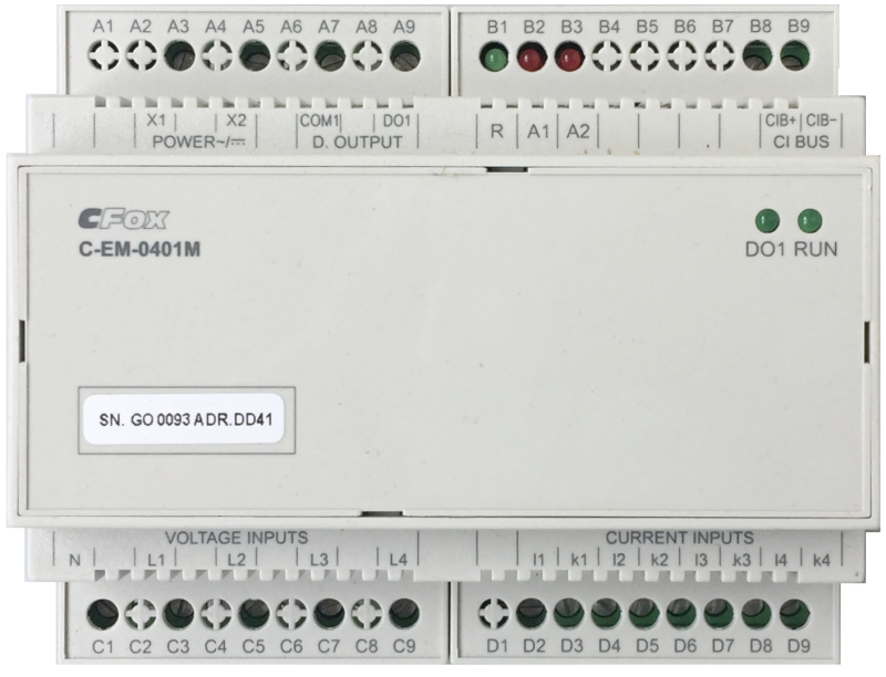
The basic diagnostics are performed internally and the measurement results are available in the relevant registers of the Mosaic environment. The status of the module is indicated by three green LEDs; two are located on the front panel (RUN and DO1), the third green LED (R) is located at the terminal level for CIB connection. After connecting the CIB bus, the green RUN LED lights up, which indicates the presence of the supply voltage on the CIB interface. When communication between the module and the central unit is established, the RUN LED flashes. A lit green LED DO1 signals the closing of the switching contact of the relay output. The third green LED R signals the connection of the auxiliary supply voltage and at the same time the status of the module at the speed of flashing. Immediately after connecting the voltage, the LED flashes quickly (once every 400 ms) for about 10 seconds. The module is being initialized at this time. Completion of initialization is indicated by a slow flashing diode (once every 2 s) and now the module is ready to perform its normal operation. The two red LEDs (A1 and A2) are for service purposes only. |
| Maintenance | |
| Description | The module does not require any maintenance under general installation conditions. The operations in which a part of the module has to be dismantled must always be carried out with the supply voltage disconnected. |
| Notice | Because the module contains semiconductor components, it is necessary to follow the principles for working with electrostatic sensitive components when handling the removed cover. It is not allowed to directly touch the printed circuit boards without protective measures !!! |
| Warranty | |
| Generally | Warranty and complaint conditions are governed by the Terms and Conditions of Teco a.s. |
| Notice | You must meet all the conditions of this documentation before turning on the system. The system must not be put into service unless it has been verified and confirmed that the machinery meets the requirements of Directive 89/392 / EEC, in so far as it applies to it. Documentation subject to change. |
HW documentation
C-EM-0401M - Basic documentation
855.07 kB, (CS, EN)
C-EM-0401M-S - Basic documentation
973.98 kB, (EN)
User manuals
Peripheral module on CIB-Common Installation Bus(R) (cs), TXV00413_01
14.01 MB
Peripheral modules on the CIB Common Installation Bus(R) (en), TXV00413_02
13.94 MB, (EN, RU, DE, UA)
Files for designers
C-EM-0401M - Technical drawing M01 DXF
504.55 kB
C-EM-0401M - Technical drawing M01 DWG
149.96 kB
C-EM-0401M - Technical drawing S01 DWG
49.40 kB
C-EM-0401M - Technical drawing S01 DXF
63.96 kB
EC - Declaration of Conformity
Foxtrot - EC Declaration of conformity
295.20 kB, (EN, RU, DE, UA)
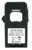
JS17F-050/100mA
JS17F-050/100mA
JS17F-050/100mA; Split-core current transformer for TXN 133 22.9-, 50 A, hole 17x17 mm
- Power dissipation of modules for calculation of switchboard heating - ...x U, 4x I, 4x bushing transformer JP5W C-EM-0401M-P035 4,0 W TXN 133 22.90 C-EM-0401M-S; CIB fast electricity meter, 230 V AC/DC power supply, 4x U, 4x I (100 mA), 1x RO; for measuring transformers wi...
- C-EM-0401M - measurement of production and consumption of el. energy, 3f fast measurement - ...ly older versions only in version C-EM-0401M-P035 (35 A die-cut transformer). Other variants are replaced by a newer version C-EM-0401M-S (order no. TXN 133 22.90), in which the customer chooses suitable current transformers with a 100 mA outp...
No data available.