


OS-8410TXN 184 10
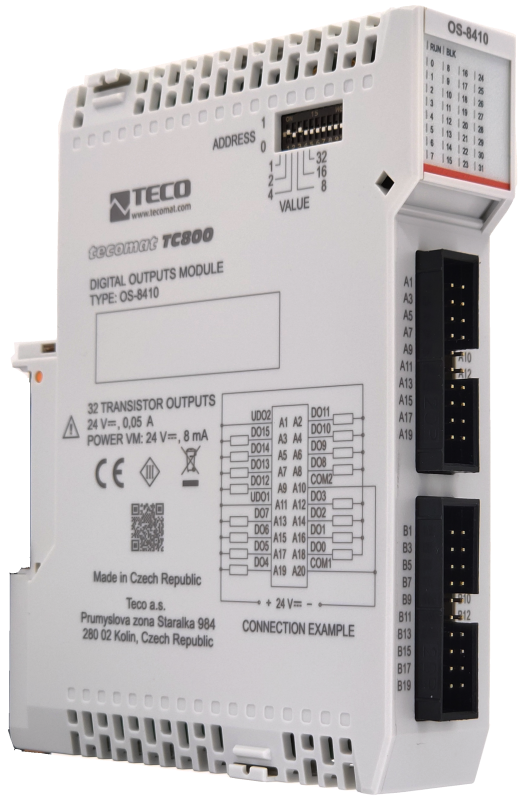
OS-8410; 32x DO, GO, 24 V DC, 0.05 A, for external modules OS-04xx
| DI | |
|---|---|
| DI/AI | |
| DO | 32x DO |
| AI | |
| AO | |
| COM | 1x TCL3 |
| SENSOR |
| Picture | Variant | Variant description |
|---|---|---|

|
OS-8410 |
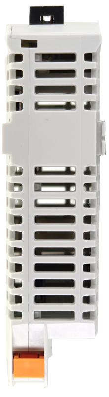
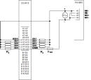
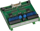
The peripheral module OS-8410 is intended for controlling up to 32 loads of 24 V DC / 0.05 A - mainly external modules on the DIN rail of the OS-04xx or OR-04xx series. The outputs are implemented by semiconductor switches that switch against the COM (minus) common terminal. The module is galvanically isolated from other PLC circuits. It is fitted with two connectors, each of which has 16 outputs. It contains intelligent output circuits that require an external 24 V DC supply voltage to be connected.
| Order num. | TXN 184 10 |
|---|---|
| Teco code | TXN 184 10 |
| Categories | TC800 - I / O expansion modules |
| Tags | - |
| COM - System buses | |
|---|---|
| TCL3 - system I/O bus | 1x TCL3 slave |
| DO/RO - Organization of binary outputs | |
| Total number of binary outputs | 32 |
| Number of binary output groups | 1 |
| Organization of binary outputs into groups | 32x DO (DO0-DO31) |
| DO - Parameters of binary transistor outputs (group A) | |
| Parameters valid for the terminals | DO0-DO31 |
| Number of transistor outputs | 32 |
| Number of output groups | 1 |
| Number of outputs in group | 32 |
| Organization of transistor outputs into groups | 32x DO (DO0-DO31) |
| Common group conductor | COM1 |
| Output type | transistor output |
| Galvanic separation from internal circuits | Yes |
| Diagnostics | indication of energized output by LED on module panel |
| Switching voltage | 9 - 30 V DC |
| Switching current, output load | 0,05 A max. |
| Group current | 0,4 A max. |
| Switching time | 400 μs max. |
| Opening time | 400 μs max. |
| Residual current | 300 μA max. |
| Short circuit protection | No |
| Treatment of inductive load | External RC element, varistor (AC), diode (DC) |
| Reverse polarity protection | Yes - The circuit will be inactive, the loads will be closed, current will flow through the protection diodes of the circuit. |
| Initial peak current tripping time | typ. 4 ms |
| Power supply | |
| Supply voltage UVM, UVIO, nominal value | 24 V DC |
| Supply voltage UVM, UVIO, allowed range | 20 - 30 V DC |
| IVM supply current at UVM = 24 V | 10 mA |
| Max. power consumption at the VM level | 0,2 W |
| Module thermal/power loss | 1,8 W |
| Bridging a power failure | 40 ms max. (Ui=170 V AC, Io=2.2 A) |
| Galvanic separation of power supply from internal circuits | Yes |
| Size and weight | |
| Weight approx. | 85 g |
| Product dimensions (width x height x depth) | 12 x 118 x 105 mm |
| Operating conditions, product standards | |
| Product standard | ČSN EN 61131-2:2008 (idt IEC 61131-2:2007) - Programmable control units |
| Protection class of electrical object | III, according to ČSN EN 61140 ed.3: 2016 (idt IEC 61140:2016) |
| IP rating (Ingress Protection) according to ČSN EN 60529: 1993 (idt IEC 529: 1989) | IP20 |
| Operating areas | Normal, acc. ČSN 33 2000-1 ed.2: 2009 (mod IEC 60354-1:2005) |
| Degree of pollution | 2, according to ČSN EN 60664-1 ed.2: 2008 (idt IEC 60664-1: 2007) |
| Overvoltage category installation | II, according to EN 60664-1 ed_2: 2008 (idt IEC 60641-1: 2007) |
| Type of device | Built-in |
| Working position | Vertical |
| Type of operation (operating frequency) | Continuous |
| Ambient operating temperatures | -20 °C to + 55 °C |
| Operating relative humidity | from 10 % up to 95 % without condensation |
| Operating atmospheric pressure | min. 70 kPa (<3,000 m above sea level) |
| Storage temperatures | –25 °C to +70 °C |
| Storage relative humidity | Max. 80% without vapor condensation |
| Storage environment | Dry, clean areas without conductive dust, aggressive gases or acid vapors for a period not exceeding the warranty period. |
| Transport temperatures | -25°C to -70°C |
| Transport environment | Covered means of transport, transport packaging must not be exposed to the effects of rain and snow |
| Electromagnetic compatibility, Mechanical endurance | |
| Electromagnetic compatibility / Emission | A, according to EN 55032 ed. 2: 2017 (idt CISPR 32: 2015) |
| Emmisions - note | In premises where the use of radio and television receivers can be expected to be used a distance of 10 m from these devices may cause radio interference. In such a case, the user may be required to take appropriate action. |
| Electromagnetic compatibility / Immunity | min. as required by EN 61131-2: 2007 |
| Sinusoidal vibration endurance | 10 Hz to 57 Hz amplitude 0.075 mm, 57 Hz to 150 Hz acceleration 1 G, according to Fc according to ČSN EN 60068-2-6 ed.2:2008 (idt IEC 60068-2-6:2007), 10 cycles in each axis . |
| Packaginng, transportation, storage | |
| Description | The module is packed in a paper box. This documentation is also part of the package. The outer packaging is carried out according to the scope of the order and the method of transport in a transport package provided with labels and other data necessary for transport. The product must not be exposed to direct weather conditions during transport and storage. Malting of the product is only allowed in clean rooms without conductive dust, aggressive gases and vapors. The most suitable storage temperature is 20 ° C |
| Installation | |
| Assembly description | The installation of the TC800 system module is carried out by sliding it perpendicularly onto the DIN rail ČSN EN 50022 with busbar and locking latch in the lower part of the module. A more detailed description and mechanical drawings with dimensions are given in the documentation TXV 004 72. |
| Connection | |
| Warning | All external circuits connected to the module must meet the conditions for SELV circuits! |
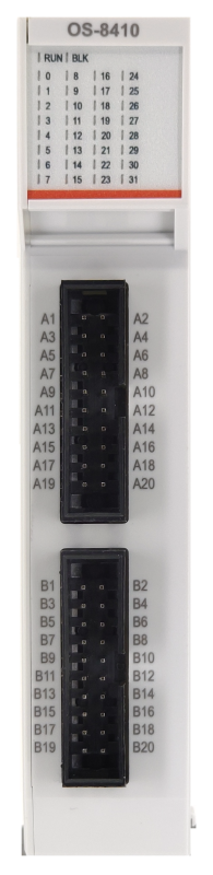
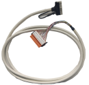
| Connection description | The module is fitted with two 16-pin connectors for connecting OS-04xx modules via cables. |
| Power connection | Via system bus + I/O connector |
| Connection of inputs / outputs | Strip wires 0.15 / 0.5 mm2 |
| Connector coding | No |
| Module installation tools | (-) 2 mm, flat screwdriver |
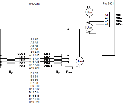
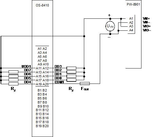
| Connection description | An example of module connection is shown in the following figure. |
| Module operation | |
| Module configuration | The module is operated, set up and diagnosed from the Mosaic development environment. |
| Commissioning | On the module, the DIP switch in the left part of the case sets a unique address within one frame. The module is fully ready for operation after inserting it into the frame and turning on the power supply. |
| Module diagnostics | The basic diagnostic system of the module is part of its standard software. It has been in operation since the module power was turned on and works independently of the user. Diagnosed error states of the module and connected peripheral modules of the assembly are signaled in the status word of the module and on the module panel |
| Maintenance | |
| Description | The module does not require any maintenance under general installation conditions. The operations in which a part of the module has to be dismantled must always be carried out with the supply voltage disconnected. |
| Notice | Because the module contains semiconductor components, it is necessary to follow the principles for working with electrostatic sensitive components when handling the removed cover. It is not allowed to directly touch the printed circuit boards without protective measures !!! |
| Warranty | |
| Generally | Warranty and complaint conditions are governed by the Terms and Conditions of Teco a.s. |
| Notice | You must meet all the conditions of this documentation before turning on the system. The system must not be put into service unless it has been verified and confirmed that the machinery meets the requirements of Directive 89/392 / EEC, in so far as it applies to it. Documentation subject to change. |
HW documentation
OS-8410 - Basic documentation
1.47 MB, (EN)
Files for designers
TC800 - library of elements in DXF and DWG formats, v. 2025/01
493.14 kB
TC800 - element library for SchemataCAD, v. 2025/01
130.34 kB
EC - Declaration of Conformity
TC800 - CE declaration of conformity (cs)
292.20 kB
TC800 - CE Declaration of Conformity (en)
709.29 kB

OS-0425
TXN 104 25
OS-0425, 16xDO, 230VDC/0.5A, SSR DC, with output protection, direct connection of the load

OS-0426
TXN 104 26
OS-0426, 16xDO, 230VAC/2A SSR AC, with output protection, direct connection of the load


OR-0424
TXN 104 24
OR 0424, 2x8RO, 230VAC/4A, Relays with output protection with RC, grouped contacts


KB-0213
4219 103 0003.30
KB-0213, Cable for external AI modules IT-04xx, shielded (W3.5/2x10 and free end with crimp sleeves), 3m
- Binary output module OS-8410 - The OS-8410 module is designed to control up to 32 loads of 24 V DC / 0.05 A - especially external modules on the DIN rail series OS-04xx or OR-04xx. The outputs are realized by semiconductor switches. The module is equipped with two connectors, t...
- Examples of power connections for TC800 modules - ...it requires to supply 24 VDC to the connector (UDI1 and COM1), the COM1 terminal is also a common terminal for DIx. The OS-8410 module has the power supply of the IO part completely separated from all the circuits of the system, so it requires t...
- TC800 power supply sizing calculation and heat loss - ...OS-8404 TXN 184 04 2 0,27 W 0 W 3 W 3 W OS-8410 TXN 184 10 2 0,2 W 0,0 W 1,8 W 1,8 W &nb...
- TECOMAT TC800 SYSTEM FEATURES - ...Binary input module IB-8310 Binary output module OS-8401 Binary output module OS-8402 Binary output module OS-8410 Binary output module OR-8450 TC800 system bus The individual modules of the system are enclos...
No data available.