


C-SI-0300ITXN 143 38
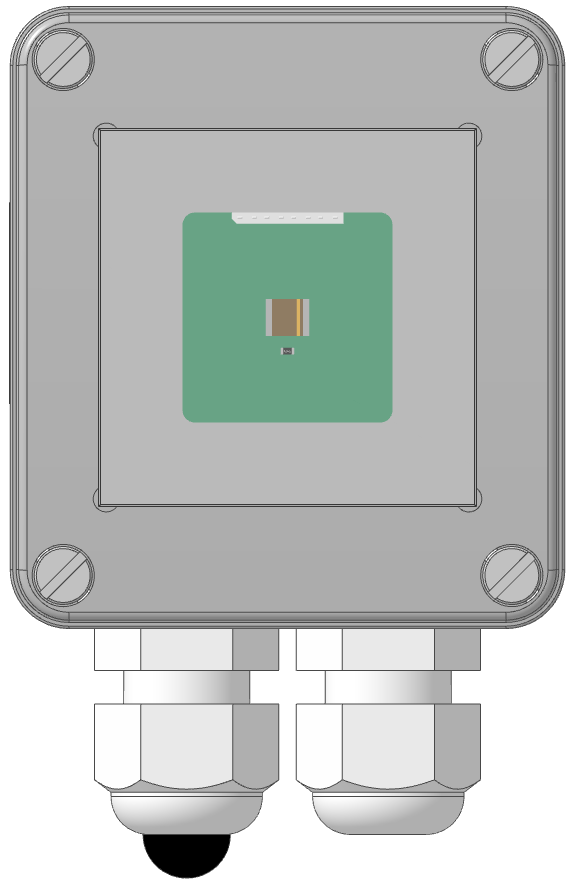
C-SI-0300I; CIB, Solar radiation sensor, IP65
| DI | |
|---|---|
| DI/AI | 3x DI/AI |
| DO | |
| AI | |
| AO | |
| COM | 1x CIB slave |
| SENSOR | solar radiation sensor |
| Picture | Variant | Variant description |
|---|---|---|

|
C-SI-0300I |
Module with 3 universal AI/DI inputs, possibility of connecting an anemometer and with integrated temperature and solar radiation sensor.
| Order num. | TXN 143 38 |
|---|---|
| Teco code | TXN 143 38 |
| Categories | CFox - Outdoor modules, IP54 / 65 |
| Tags | IP-65 |
| COM - System buses | |
|---|---|
| CIB - Common Installation Bus (R): Installation I/O bus | 1x CIB slave |
| Solar radiation sensor parameters | |
| Solar radiation - measurement range | 0 to 1500 W/m² |
| DI - Organization of binary inputs | |
| Total number of binary inputs | 3 |
| Number of groups of binary inputs | 1 |
| Organization of binary inputs into groups | 3x DI (DI/AI1 - DI/AI3) |
| DI - Parameters of binary inputs DC (group A) | |
| Parameters valid for inputs on the terminals | 3x DI/AI1 - DI/AI3 |
| Number of inputs in group | 3 |
| Common wire | GND - module ground |
| Combined input type | DI/AI Active, for sensing potential-free contacts and measuring resistance sensors |
| Galvanic isolation of inputs from internal/peripheral circuits | No |
| Delay from log. 0 to log. 1 | 200 μs |
| Delay from log. 1 to log. 0 | 200 μs |
| Max. measuring voltage on the connected contact | 3,5 V DC |
| Internal input resistance | 2 kΩ |
| Max. resistance for closed contact, log. 1 | < 0,5 kΩ |
| Min. resistance for open contact, log. 0 | > 4,7 kΩ |
| Anemometer mode | Input DI/AI1 0 - 2000 Hz |
| AI - Organization of analog inputs | |
| Total number of analog inputs | 3 |
| Number of inputs per group | 3 |
| Number of analog input groups | 1 |
| Organization of analog inputs into groups | 3x DI (DI/AI1 - DI/AI3) |
| Input type | AI / DI - combined |
| Common wire | GND terminal |
| Galvanic separation from internal circuits | No |
| Diagnostics | overload signaling in status word |
| Digital resolution | 12 bit |
| AI - Analog Input Ranges | |
| Parameters valid for inputs on the terminals | DI/AI1 - DI/AI3 |
| Voltage | 0-2 V |
| Passive sensor | Pt1000, W100 = 1,385 (-90 to +320 °C) |
| Passive sensor | Pt1000, W100 = 1,391 (-90 to +320 °C) |
| Passive sensor | Ni1000, W100 = 1,500 (–60 to +200 °C) |
| Passive sensor | Ni1000, W100 = 1.617 (-60 to +200 °C) |
| Passive sensor | Resistance transmitter 0-100 kOhm |
| Passive sensor | KTY81-121; PTC thermistor (-55 to + 125 °C) |
| Passive sensor | NTC Thermistor 10k / 25 °C (-40 to + 125 °C) |
| Passive sensor | NTC Thermistor 12k / 25 °C (-40 to + 125 °C) |
| Power supply | |
| Supply voltage, tolerances | 24/27 V DC from CIB bus |
| Power supply from CIB - maximum current consumption (mA) | 9 mA |
| Size and weight | |
| Weight approx. | 140 g |
| Product dimensions (width x height x depth) | 65 × 100 × 40 mm |
| Operating conditions, product standards | |
| Product standard | ČSN EN 60730-1 ed.4 :2017 (EN 60730-1:2016) -Automatic electronic control device (for household and similar purposes) |
| Protection class of electrical object | III, according to ČSN EN 61140 ed.3: 2016 (idt IEC 61140:2016) |
| IP rating (Ingress Protection) according to ČSN EN 60529: 1993 (idt IEC 529: 1989) | IP65 |
| Operating areas | Normal, acc. ČSN 33 2000-1 ed.2: 2009 (mod IEC 60354-1:2005) |
| Degree of pollution | 2, according to ČSN EN 61131-2 |
| Overvoltage category installation | III, according to EN 60664-1 ed_2: 2008 (idt IEC 60641-1: 2007) |
| Type of device | Outdoor |
| Working position | Vertical (grommets down) |
| Ambient operating temperatures | –25 °C až +75 °C |
| Operating atmospheric pressure | min. 70 kPa (<3,000 m above sea level) |
| Storage temperatures | –25 ° C to + 85 ° C |
| Electromagnetic compatibility, Mechanical endurance | |
| Electromagnetic compatibility / Emission | ČSN EN 55022 ed2:2007 (mod CISPR22:2005) |
| Electromagnetic compatibility / Immunity | min. according to ČSN EN 60730-1 ed.2: 2001 |
| Sinusoidal vibration endurance | 10 Hz to 57 Hz, amplitude 0,075 mm, 57 Hz to 150 Hz, acceleration 1 G (Fc test according to EN 60068-2-6: 1997 (idt IEC 68-2-6: 1995), 10 cycles per axis.) |
| Packaginng, transportation, storage | |
| Description | The module is packed in a cardboard box. The outer packaging is carried out according to the scope of the order and the method of transport in a transport container provided with labels and other information necessary for transport. Transport from the manufacturer is carried out in the manner agreed upon when ordering. Transport of the product by the customer's own means must be carried out by covered means of transport, in the position specified by the label on the packaging. The box must be stored in such a way as to prevent spontaneous movement and damage to the outer packaging. The product must not be exposed to direct weather conditions during transport and storage. The product is only allowed to be stored in clean rooms without conductive dust, aggressive gases and vapors. The most suitable storage temperature is 20°C |
| Installation | |
| Assembly description | The module is mounted vertically on the support surface with the cable gland facing downwards. The assembly (basic module and possibly peripheral modules) is installed according to TXV 004 13. |
| Connection | |
| Connection of power and system communication | 2 wire cable 4.5 - 7mm, PG9 bushing |
| Connection of power and system communication | terminal block with spring clamp 0.2-1.5 mm² |
| Module operation | |
| Module configuration |
Module configuration The module is operated, set and diagnosed from the Mosaic development environment. Commissioning The module is operated, set and diagnosed from the MOSAIC programming environment or other parameterization software. The module is ready for operation after connecting the supply voltage and the CIB bus. The HW address is listed on the label on the module. Module diagnostics Basic diagnostics are performed internally and the result is available in the relevant registers of the Mosaic environment. |
| Maintenance | |
| Description | The module does not require any maintenance under general installation conditions. The operations in which a part of the module has to be dismantled must always be carried out with the supply voltage disconnected. |
| Notice | Because the module contains semiconductor components, it is necessary to follow the principles for working with electrostatic sensitive components when handling the removed cover. It is not allowed to directly touch the printed circuit boards without protective measures !!! |
| Warranty | |
| Generally | Warranty and complaint conditions are governed by the Terms and Conditions of Teco a.s. |
| Notice | You must meet all the conditions of this documentation before turning on the system. The system must not be put into service unless it has been verified and confirmed that the machinery meets the requirements of Directive 89/392 / EEC, in so far as it applies to it. Documentation subject to change. |
User manuals
Peripheral module on CIB-Common Installation Bus(R) (cs), TXV00413_01
14.01 MB
Peripheral modules on the CIB Common Installation Bus(R) (en), TXV00413_02
13.94 MB, (EN, RU, DE, UA)
HW documentation
C-SI-0300I - Basic documentation
278.37 kB, (EN)
Files for designers
Foxtrot 2 - library of elements in DXF and DWG formats, v. 2025/08.
21.80 MB
Foxtrot 2 - element library for SchemataCAD, v. 2025/08.
6.96 MB
EC - Declaration of Conformity
Foxtrot 2 - EC Declaration of conformity (en)
590.59 kB, (EN, RU, DE, UA)
- C-SI-0300I - Solar Radiation Sensor - ...for measuring wind speed). Table of basic module parameters and user manual: https://catalog.tecomat.cz/en/product/c-si-0300i The C-SI-0300I module replaces the previously supplied C-IT-0200I-SI and S-SI-01I modules. The mechanical d...
No data available.