


C-IT-0200ITXN 133 09
C-IT-0200I; CIB, 2x AI, 0-10V, 4-20mA, RTD, TC, IP65
| DI | |
|---|---|
| DI/AI | |
| DO | |
| AI | 2x AI (V, A, RTC, thermocouples) |
| AO | |
| COM | 1x CIB slave |
| SENSOR | Internal temperature |
| Picture | Variant | Variant description |
|---|---|---|

|
C-IT-0200I |
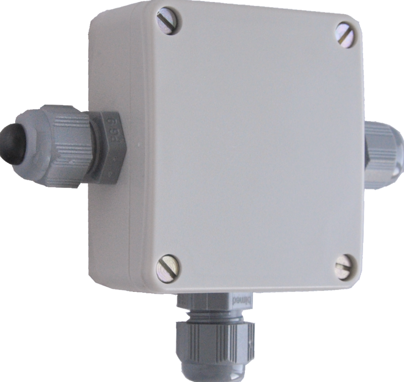
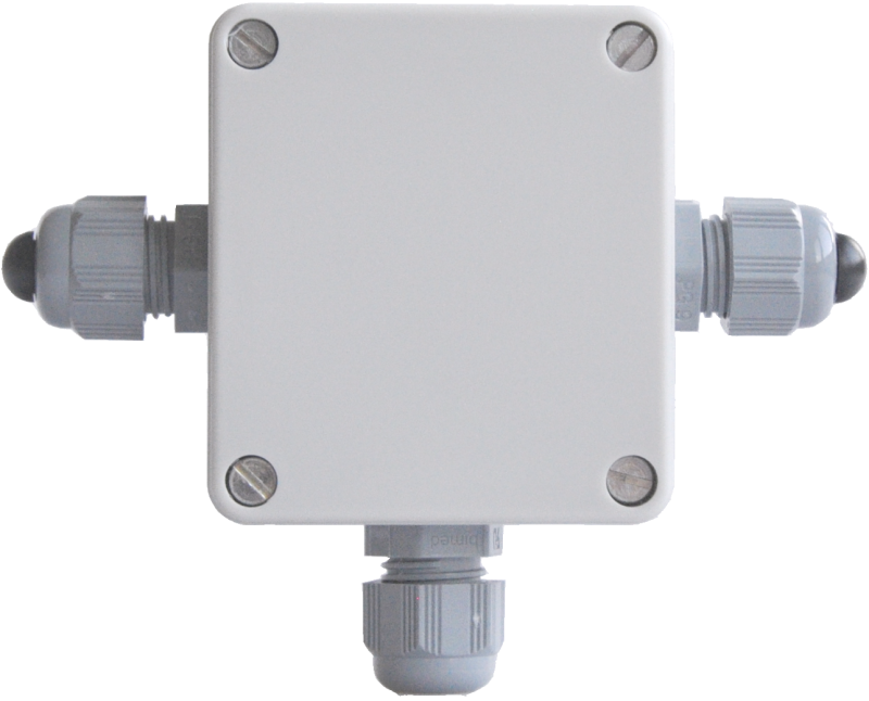
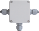
The module contains 2 universal analog inputs for general use, connects to the CIB Common Installation Bus® and has a high coverage for use in outdoor conditions.
It allows to measure voltage, current, resistance, resistance temperature sensors and thermocouples.
The selection of the type and range of measurement is done by jumpers.
The firmware of the module linearizes the characteristics of the resistance sensor, optimizes the accuracy of the measurement and converts it to the temperature, which is then transmitted as a number to the central unit.
No special wiring is required to supply the current loops, the power supply is generated locally from the CIB bus.
High coverage allows you to install the module as close as possible to the measured quantity.
The module can be used to measure even very low voltages due to the high input resistance
| Order num. | TXN 133 09 |
|---|---|
| Teco code | TXN 133 09 |
| Categories | CFox - Outdoor modules, IP54 / 65 |
| Tags | - |
| COM - System buses | |
|---|---|
| CIB - Common Installation Bus (R): Installation I/O bus | 1x CIB slave |
| AI - Organization of analog inputs | |
| Total number of analog inputs | 2 |
| Number of inputs per group | 2 |
| Number of analog input groups | 1 |
| Input type | With common clamp |
| Common wire | Minus |
| Galvanic separation from internal circuits | No |
| External power supply | No |
| Digital resolution | 16 bit |
| Converter type | sigma-delta |
| AI - Analog Input Ranges (Group A) | |
| Parameters valid for inputs on the terminals | AI1, AI2 |
| Voltage | 0-10 V |
| Voltage | 0-5 V |
| Voltage | ±2 V |
| Voltage | ±1 V |
| Voltage | ±0,1 V |
| Voltage | HI ±1V |
| Voltage | HI ±100 mV |
| Thermocouple | Type J (-210 ° C to 1200 ° C) |
| Thermocouple | Type K (–200 to +1372 ° C) |
| Thermocouple | Type R (-50 to +1768 ° C) |
| Thermocouple | Type N (-200 ° C ÷ 1300 ° C) |
| Thermocouple | Type T (-200 ° C ÷ 400 ° C) |
| Thermocouple | Type B (250 ° C ÷ 1820 ° C) |
| Thermocouple | Type S (-50 ° C ÷ 1768 °C) |
| High ohmic input (thermocouples and HI ± 1 V and HI ± 100 mV) | > 4 MOhm |
| Input impedance in the voltage signal range | > 54,6 kΩ |
| Voltage input error - max. error at 25 ° C | ± 2.0% of full scale |
| Voltage input error - temperature coefficient | ± 0,1% of full scale |
| Voltage input error - non-linearity | ± 0.1% of full scale |
| Voltage input error - repeatability under steady state conditions | 0.5% of full scale |
| Thermocouple cold end compensation | Yes - (except type B) |
| Additive error analog input error due to cold junction compensation (thermocouple measurement only) | < 3 % of the internal thermometer range |
| Ccurrent | 0 - 20 mA |
| Current | 4-20 mA |
| Input impedance in the current signal range | 50 Ω |
| Current input error - maximum error at 25 ° C | ±2% of full scale |
| Error current input - temperature coefficient | ± 0,1% of full scale |
| Error current input - nonlinearity | ± 0,1% of full scale |
| Error current input - repeatability at steady-state conditions | 0.5% of full scale |
| Passive sensor | Pt1000, W100 = 1,385 (-90 to +320 °C) |
| Passive sensor | Pt1000, W100 = 1,391 (-90 to +320 °C) |
| Passive sensor | Ni1000, W100 = 1,500 (–60 to +200 ° C) |
| Passive sensor | Ni1000, W100 = 1.617 (-60 to +200 ° C) |
| Passive sensor | Resistance transmitter 0-200 kOhm |
| Passive sensor | KTY81-121; PTC thermistor (-55 to + 125 °C) |
| Passive sensor | NTC Thermistor 12k / 25 °C (-40 to + 125 °C) |
| Input impedance in signal range RTD | > 4,7 kΩ |
| Resistance measurement error - maximum error at 25 ° C | ± 2% of full scale |
| Resistance measurement error - temperature coefficient | ± 0,1% of full scale |
| Resistance measurement error - non-linearity | ± 0.1% of full scale |
| Resistance measurement error - repeatability at steady conditions | 0.5% of full scale |
| Output for supplying measuring current loops | |
| Short circuit protection | No |
| Parameter des Temperatursensors | |
| Temperature - Measurement range | –20 °C ÷ +80 °C |
| Temperature - Measurement error | <4% of range |
| Power supply | |
| Supply voltage, tolerances | 24/27 V DC from CIB bus |
| Maximum power input | 1,5 W |
| Power supply from CIB - typical current consumption (mA) | 15 mA - without power supply for measuring loops |
| Power supply from CIB - maximum current consumption (mA) | 60 mA |
| Power supply from CIB - internal protection | No |
| Internal power supply for the current loop | Yes - from CIB power supply |
| Internal power supply for the current loop - short-circuit protection | No |
| Size and weight | |
| Weight approx. | 125 g |
| Product dimensions (width x height x depth) | 125 x 100 x 38 mm |
| Operating conditions, product standards | |
| Product standard | ČSN EN 60730-1 ed. 2:2001 (mod IEC 60730-1:1999) |
| Protection class of electrical object | I, according to ČSN EN 61140: 2003 (idt IEC 61140: 2001) |
| IP rating (Ingress Protection) according to ČSN EN 60529: 1993 (idt IEC 529: 1989) | IP65 |
| Operating areas | Normal, acc. ČSN 33 2000-1 ed.2: 2009 (mod IEC 60354-1:2005) |
| Degree of pollution | 1, according to ČSN EN 60664-1 ed.2:2008 ( idt IEC 60664-1:2007) |
| Overvoltage category installation | II, according to EN 60664-1 ed_2: 2008 (idt IEC 60641-1: 2007) |
| Type of device | On the wall |
| Working position | Any |
| Type of operation (operating frequency) | Continuous |
| Ambient operating temperatures | -10 °C to + 55 °C |
| Operating relative humidity | from 10 % up to 95 % without condensation |
| Operating atmospheric pressure | min. 70 kPa (<3,000 m above sea level) |
| Storage temperatures | –25 °C to +70 °C |
| Electromagnetic compatibility, Mechanical endurance | |
| Electromagnetic compatibility / Emission | ČSN EN 55022 ed2:2007 (mod CISPR22:2005) |
| Electromagnetic compatibility / Immunity | min. according to ČSN EN 60730-1 ed.2: 2001 |
| Sinusoidal vibration endurance | 10 Hz to 57 Hz, amplitude 0,075 mm, 57 Hz to 150 Hz, acceleration 1 G (Fc test according to EN 60068-2-6: 1997 (idt IEC 68-2-6: 1995), 10 cycles per axis.) |
| Packaginng, transportation, storage | |
| Description | The module is packed in a paper box. This documentation is also part of the package. The outer packaging is carried out according to the scope of the order and the method of transport in a transport package provided with labels and other data necessary for transport. The product must not be exposed to direct weather conditions during transport and storage. Malting of the product is only allowed in clean rooms without conductive dust, aggressive gases and vapors. The most suitable storage temperature is 20 ° C |
| Connection | |
| Connection of power and system communication | terminal block with spring terminal 1.5 mm2, push-in |
| Connection of inputs / outputs | terminal block with spring terminal 1.5 mm2, push-in |
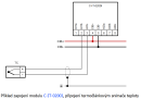
| Module connection | The module is implemented as a CIB bus module, which provides communication. The power supply of the module is from an external source. The CIB bus can have any topology and branching up to a distance of 500 m and up to 32 units on one CIB branch. The CIB bus master is the FOXTROT base unit or module, for example CF-1141. Further information can be found in the manual Peripheral modules on the CIB bus TXV 004 13. An example of the module connection is shown in the following figure |
| Module operation | |
| Module configuration |
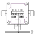
The C-IT-0200I module allows the measurement of voltage, current and resistance temperature. The measuring range is configured by connecting the sensor to the appropriate terminals and setting the jumpers. Examples of terminal connections and jumper configurations for each range are shown in Figure 2. When selecting the measuring range, it is also necessary to select the appropriate range in the module configuration in the Mosaic environment, or possibly other configuration SW. |
| Commissioning | The module is operated, set and diagnosed from the MOSAIC programming environment or other parameterization software. The module is ready for operation after connecting the supply voltage and the CIB bus. The HW address is indicated on the label on the module. |
| Module diagnostics | The basic diagnostics is performed internally and the result is available in the relevant registers of the Mosaic environment. |
| Maintenance | |
| Description | The module does not require any maintenance under general installation conditions. |
| Notice | Because the module contains semiconductor components, it is necessary to follow the principles for working with electrostatic sensitive components when handling the removed cover. It is not allowed to directly touch the printed circuit boards without protective measures !!! |
| Warranty | |
| Generally | Warranty and complaint conditions are governed by the Terms and Conditions of Teco a.s. |
| Notice | You must meet all the conditions of this documentation before turning on the system. The system must not be put into service unless it has been verified and confirmed that the machinery meets the requirements of Directive 89/392 / EEC, in so far as it applies to it. Documentation subject to change. |
HW documentation
C-IT-0200I - basic documentation
213.61 kB
User manuals
Peripheral module on CIB-Common Installation Bus(R) (cs), TXV00413_01
14.01 MB
Peripheral modules on the CIB Common Installation Bus(R) (en), TXV00413_02
13.94 MB, (EN, RU, DE, UA)
Files for designers
Foxtrot 2 - library of elements in DXF and DWG formats, v. 2025/08.
21.80 MB
Foxtrot 2 - element library for SchemataCAD, v. 2025/08.
6.96 MB
EC - Declaration of Conformity
Foxtrot - EC Declaration of conformity
295.20 kB, (EN, RU, DE, UA)
- C-IT-0200I - The C-IT-0200I is a module on the CIB bus containing 2 analogue inputs. The inputs can be configured for measurement of resistance temperature sensors, thermocouples, resistance, voltage or current. The module power supply (including powerin...
- Measuring solar radiation, the CFox sensor C-IT-0200I-SI - Measuring solar radiation can be done by the C-IT- 0200I-SI module, which comprises the inner part of the C-IT-0200I module fitted into the S-SI-01I sensor. The solar radiation sensor uses for its own measurement of intensity a mon...
- Measurement of high temperatures up to 1100 ° C, TC, C-IT-0200I - ...nt can be measured using temperature sensors equipped with a thermocouple sensor. Thermocouples can be measured with the C-IT-0200I module (see the following example), or we can use the analog input module IT-1605 (peripheral mod...
- C-SI-0300I - Solar Radiation Sensor - ...manual: https://catalog.tecomat.cz/en/product/c-si-0300i The C-SI-0300I module replaces the previously supplied C-IT-0200I-SI and S-SI-01I modules. The mechanical dimensions, mounting, and terminals are identical. Fig. 1 Terminal...
- S-SI-01I - ...gue inputs (measuring of the output voltage of the sensor itself and the NTC 12k temperature sensor) of the modules C-IT-0200I , C-HM-xxxxM, R-HM-xxxxM, C-AM-0600I. The level of intensity (W/m 2 ) is calculated using...
- Measuring pH and Redox (chlorine) - ...The pH and REDOX can also be measured by the SEKO company probes. Both probes can be connected simultaneously to one C-IT-0200I module, but with some risk of mutual influence of the two probes. It is necessary to verify, or find, the optimu...
- Measuring REDOX - ...ing on their selection and installation. The following figure illustrates the wiring of the Pt 2+P probe to the C-IT-0200I module. The best possible measurement conditions can be ensured by using only one input of the module for m...
- Measuring pH - ...on their selection and installation. The following figure illustrates the connection of the pH 2+L probe to the C-IT-0200I module. The best possible measurement conditions can be ensured by using only one input of the module for m...
- Swimming pool technology - ...hese probes have various types of outlets, which are mostly current loops or voltage outputs. It is recommended to use the C-IT-0200I module to process the signal from these probes, as it is suitable both for the measurement of the current loop a...
- Continuous measurement of water pressure in the heating circuit - ...to 600 kPa. The connection is designed as a standard current loop 4 to 20mA; it can be connected e.g.to the C-IT-0200I module (see an example in Chapter 11.8.1 ). The type (order n...
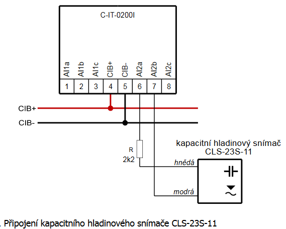
- Point level monitoring of water level in the well or in a tank - ...g. 1. Wiring of capacitive level sensor CLS-23S-11 Notes: The sensor is connected to the input of the C-IT-0200I module configured for measuring the current loop 4 ÷ 20 mA via a 2k2 serial resistor. The v...
- Continuous measurement of the water level in the well or a reservoir - ...(for atmospheric pressure compensation) and two wires (a current loop 4 ÷ 20 mA); an example of connection to the C-IT-0200I module is shown in the following figure. Fig. 1. Wiring the level meter HLM-25S ...
- Basic information about temperature sensors - ...thermocouple sensors. Tab. 5. Basic properties of thermocouples (the selection according to the module C-IT-0200I ): Type Range Usage...
- Connection of CP-1091 for efficient control of energy produced from PV and HFVE - ...bsp;bus, which is used to connect a fast electricity meter C-EM-0401M and other modules - such as solar radiation sensors C-IT-0200I-SI etc. There is also TCL2 bus master for further expansion. At the same time, the module is equipped with...
- Measuring the intensity of solar radiation - Applications for measuring solar radiation (its intensity), e.g. for the evaluation of the effectiveness of PVPS, thermal panels, optimizing heating water in thermal panels, etc., utilize the solar radiation sensors: pyranometers, solarimeters and o...
- Analog input - .../catalog.tecomat.cz/en/product/it-1604#params). And finally on CIB bus, there are analog inputs 0 -10 V available on modules C-IT-0200I (https://catalog.tecomat.cz/en/product/c-it-0200i) or C-AM-0600I (https://catalog.tecomat.cz/en/product/c-am-0600i...