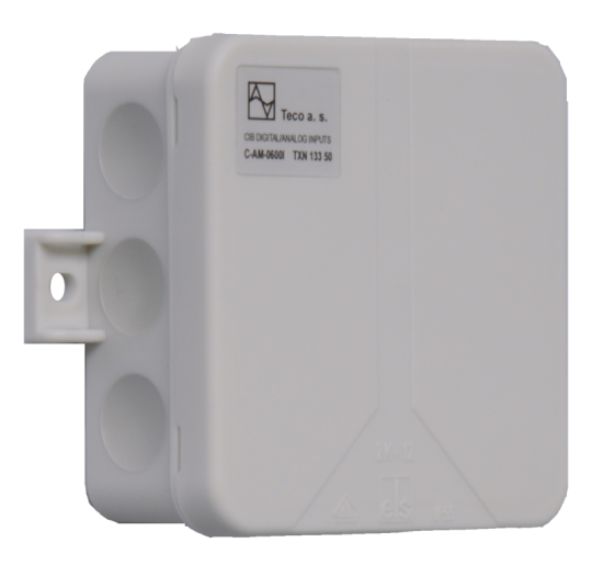
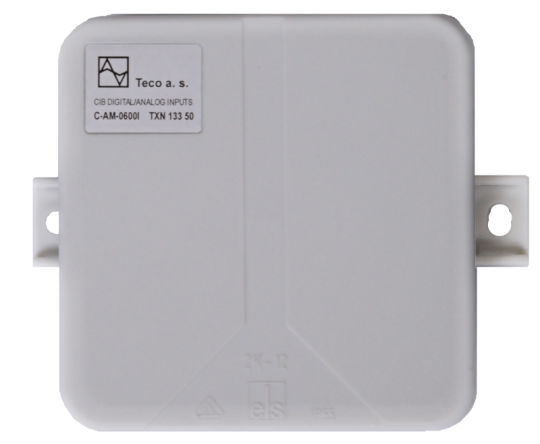
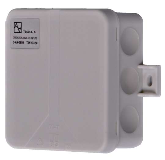
C-AM-0600ITXN 133 50
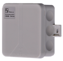
C-AM-0600I; CIB, 5xAI/DI, 1x AI analog inputs and energy metering module, IP55 protection
| DI | 5x DI/counter |
|---|---|
| DI/AI | 5x DI/AI |
| DO | |
| AI | 1x interface for TacoSetter Tronic flowmeter |
| AO | |
| COM | 1x CIB slave |
| SENSOR | Interface for TacoSetter Tronic flowmeter |
| Picture | Variant | Variant description |
|---|---|---|

|
C-AM-0600I |
C-AM-0600I - module on the CIB Common Installation Bus®, contains 5 universal inputs and 1 special interface for connecting a turbine-free TacoSetter Tronic flowmeter.
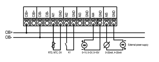
Universal inputs can be configured for measurement
Universal inputs can be configured for measurement
- resistance temperature sensors,
- Tension,
- current
- can be configured as an interface for reading pulses from energy meters, eg electricity meters, gas meters, etc.
| Order num. | TXN 133 50 |
|---|---|
| Teco code | TXN 133 50 |
| Categories | CFox - Outdoor modules, IP54 / 65 |
| Tags | - |
| COM - System buses | |
|---|---|
| CIB - Common Installation Bus (R): Installation I/O bus | 1x CIB slave |
| DI - Parameters of binary inputs DC (group A) | |
| Parameters valid for inputs on the terminals | AI1-AI5 |
| Common wire | GND - module ground |
| Combined input type | Active / passive binary input; Active when setting the range 0-10V. Passive when setting the Pt1000, Ni1000 and KTY81-121 ranges. |
| Galvanic isolation of inputs from internal/peripheral circuits | No |
| Input current at log. 1 (typ.) | 1,5 mA typ. |
| Delay from log. 0 to log. 1 | 10 ms |
| Delay from log. 1 to log. 0 | 300 ms |
| The minimum width of the captured pulse | 30 ms |
| Internal input resistance | 64,9 kΩ |
| Notice |
1) Input AI5 has a reduced voltage supply for the binary counter, which does not correspond to the S0 interface standard. 2) Digital inputs do not have their own configuration. The type of digital input can thus be selected using the appropriate analog range. 3) The type of digital input is set using the corresponding analog range when configuring the module in the Mosaic environment. The active digital input corresponds to the range 0 ÷ 10 V. The passive digital input corresponds to the ranges Pt1000, Ni1000, KTY81-121. |
| Pulse counter | |
| Reference voltage (1) |
for inputs AI1 - AI4: Typically 24 V DC (according to CIB supply voltage) |
| Reference voltage (2) |
for AI5 input Typically 7.4 V DC |
| Maximum input current | 14 mA |
| Pulse length | ≥ 30 ms |
| Maximum frequency | 20 Hz |
| Maximum resistance of the switch in the closed state | 800 Ω |
| AI - Organization of analog inputs | |
| Number of inputs per group | 5 |
| Number of analog input groups | 1 |
| AI - Analog Input Ranges (Group A) | |
| Parameters valid for inputs on the terminals | AI1- AI5 |
| Voltage | 0-10 V |
| Voltage | 0-2 V |
| Voltage | 0 -1 V |
| Voltage input error - max. error at 25 ° C | ± 2.0% of full scale |
| Voltage input error - temperature coefficient | ± 0,1% of full scale |
| Voltage input error - non-linearity | ± 0.1% of full scale |
| Voltage input error - repeatability under steady state conditions | 0.5% of full scale |
| Ccurrent | 0 - 20 mA |
| Current | 4-20 mA |
| Current input error - maximum error at 25 ° C | ±2% of full scale |
| Error current input - temperature coefficient | ± 0,1% of full scale |
| Error current input - nonlinearity | ± 0,1% of full scale |
| Error current input - repeatability at steady-state conditions | 0.5% of full scale |
| Passive sensor | Pt1000, W100 = 1,385 (-90 to +320 °C) |
| Passive sensor | Pt1000, W100 = 1,391 (-90 to +320 °C) |
| Passive sensor | Ni1000, W100 = 1,500 (–60 to +200 ° C) |
| Passive sensor | Ni1000, W100 = 1.617 (-60 to +200 ° C) |
| Passive sensor | Resistance transmitter 0-200 kOhm |
| Passive sensor | Resistance transmitter 0-450 kOhm |
| Passive sensor | KTY81-121; PTC thermistor (-55 to + 125 °C) |
| Passive sensor | NTC Thermistor 12k / 25 °C (-40 to + 125 °C) |
| Resistance measurement error - maximum error at 25 ° C | ± 2% of full scale |
| Resistance measurement error - temperature coefficient | ± 0,1% of full scale |
| Resistance measurement error - non-linearity | ± 0.1% of full scale |
| Resistance measurement error - repeatability at steady conditions | 0.5% of full scale |
| Flowmeter interface parameters | |
| Parameters valid for terminals | AV23 |
| Type of flow meter to connect | TacoSetter Tronic |
| Principle of flow measurement | Vortex in the medium |
| Integrated power supply for the flow meter | Yes - from CIB power supply |
| Flow meter supply voltage | 5 V DC |
| Typical consumption from CIB | 3 mA |
| Input for flow meter - input resistance | > 14 kΩ |
| Input for flow meter - measuring range | 0,5 ÷ 3,5 V |
| Input for flow meter - error of measuring input | 0,50 % |
| Integrated thermometer input - input resistance | > 14 kΩ |
| Integrated thermometer input - measuring range | 0,5 ÷ 3,5 V |
| Integrated thermometer input - measuring input error | 0,50 % |
| Power supply | |
| Supply voltage, tolerances | 24/27 V DC from CIB bus |
| Power supply from CIB - typical current consumption (mA) | 40 mA |
| Power supply from CIB - maximum current consumption (mA) | 80 mA |
| Internal protection | No |
| Size and weight | |
| Weight approx. | 70 g |
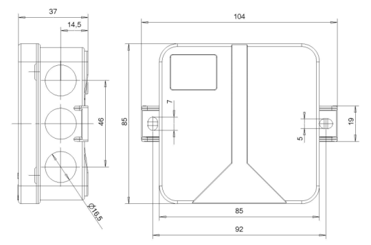
| Product dimensions (width x height x depth) | 85 x 85 x 37 mm |
| Operating conditions, product standards | |
| Product standard | ČSN EN 60730-1 ed. 2:2001 (mod IEC 60730-1:1999) |
| Protection class of electrical object | I, according to ČSN EN 61140 ed.3: 2016 (idt IEC 61140:2016) |
| IP rating (Ingress Protection) according to ČSN EN 60529: 1993 (idt IEC 529: 1989) | IP 55 |
| Operating areas | Normal, acc. ČSN 33 2000-1 ed.2: 2009 (mod IEC 60354-1:2005) |
| Degree of pollution | 1, according to ČSN EN 60664-1 ed.2:2008 ( idt IEC 60664-1:2007) |
| Overvoltage category installation | II, according to EN 60664-1 ed_2: 2008 (idt IEC 60641-1: 2007) |
| Type of device | On the wall |
| Working position | Any |
| Type of operation (operating frequency) | Continuous |
| Ambient operating temperatures | -10 °C to + 55 °C |
| Operating relative humidity | from 10 % up to 95 % without condensation |
| Operating atmospheric pressure | min. 70 kPa (<3,000 m above sea level) |
| Storage temperatures | –25 °C to +70 °C |
| Electromagnetic compatibility, Mechanical endurance | |
| Electromagnetic compatibility / Emission | B, according to EN 55032 ed. 2: 2017 (idt CISPR 32: 2015) |
| Electromagnetic compatibility / Immunity | min. according to ČSN EN 60730-1 ed.2: 2001 |
| Sinusoidal vibration endurance | 10 Hz to 57 Hz, amplitude 0,075 mm, 57 Hz to 150 Hz, acceleration 1 G (Fc test according to EN 60068-2-6: 1997 (idt IEC 68-2-6: 1995), 10 cycles per axis.) |
| Packaginng, transportation, storage | |
| Description | The module is packed in a paper box. This documentation is also part of the package. The outer packaging is carried out according to the scope of the order and the method of transport in a transport package provided with labels and other data necessary for transport. The product must not be exposed to direct weather conditions during transport and storage. Malting of the product is only allowed in clean rooms without conductive dust, aggressive gases and vapors. The most suitable storage temperature is 20 ° C |
| Installation | |
| Assembly description | Indoor wall mounting |
| Connection | |
| Connection of power and system communication | terminal block with spring terminal 1.5 mm2, push-in |
| Connection of inputs / outputs | terminal block with spring terminal 1.5 mm2, push-in |
| Specific I / O | TacoSetter Tronic flowmeter |
| Module installation tools | (-) 3 mm, flat screwdriver |
| Module connection |
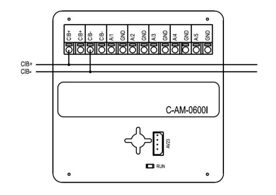
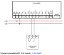
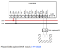
The module is implemented as a CIB bus module, which provides communication. The power supply of the module is from an external source. The CIB bus can have any topology and branching up to a distance of 500 m and up to 32 units on one CIB branch. The CIB bus master is Foxtrot base unit or external master, such as the CF-1141 module. Further information can be found in the manual Peripheral modules on the CIB TXV 004 13. An example of module connection is shown in the following figure. |
| Module operation | |
| Module configuration | The C-AM-0600I module allows the measurement of temperature, voltage, current, resistance and the number of pulses. The measuring range is selected using the module configuration menu in the Mosaic environment or possibly in another configuration SW |
| Commissioning | The module is operated, set and diagnosed from the MOSAIC programming environment or other parameterization software. The module is ready for operation after connecting the supply voltage and the CIB bus. The HW address is indicated on the label on the module. |
| Module diagnostics | The basic diagnostics is performed internally and the result is available in the relevant registers of the Mosaic environment. |
| Maintenance | |
| Description | The module does not require any maintenance under general installation conditions. |
| Notice | Because the module contains semiconductor components, it is necessary to follow the principles for working with electrostatic sensitive components when handling the removed cover. It is not allowed to directly touch the printed circuit boards without protective measures !!! |
| Warranty | |
| Generally | Warranty and complaint conditions are governed by the Terms and Conditions of Teco a.s. |
| Notice | You must meet all the conditions of this documentation before turning on the system. The system must not be put into service unless it has been verified and confirmed that the machinery meets the requirements of Directive 89/392 / EEC, in so far as it applies to it. Documentation subject to change. |
HW documentation
C-AM-0600I- Basic documentation
229.67 kB
User manuals
Peripheral module on CIB-Common Installation Bus(R) (cs), TXV00413_01
14.01 MB
Peripheral modules on the CIB Common Installation Bus(R) (en), TXV00413_02
13.94 MB, (EN, RU, DE, UA)
Files for designers
Foxtrot 2 - library of elements in DXF and DWG formats, v. 2025/08.
21.80 MB
Foxtrot 2 - element library for SchemataCAD, v. 2025/08.
6.96 MB
EC - Declaration of Conformity
Foxtrot - EC Declaration of conformity
295.20 kB, (EN, RU, DE, UA)
- Indirect connection of the C-AM-0600I input to the SP output via an auxiliary relay - The following figure shows an example of an indirect connection of one-command switching element to the C-AM-0600I module binary input, which provides the power control of the blocked appliances and also has information on the validity of the low ta...
- C-AM-0600I - The C-AM-0600I is a universal input module designed to measure temperature , pulse inputs, flowmeters and water meters, gas meters and electricity meters with the S0 output (class A, measuring current of approximately 10 mA). At the...
- Measurements of dewing (condensation of air humidity) - ...4.2 ). The resistive probe with the polymer layer ( Chap.11.4.1 ) can only be connected to the AI5 input of the C-AM-0600I module. The probe with the isolated electrodes ( Chap.11.4. 3 ) can be attached to the AI5 input of the...
- Metering the consumption of 1ph network, the 9901M and ED11.M electricity meter, measuring t - ...ver the 9901M electricity meter, and the ED11.M meter can also be used for some applications. The primary function of the C-AM-0600I modules is to connect the S0 electricity meters with a pulse output, in accordance with IEC 62053 it is class...
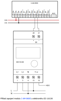
- Metering the generation and consumption of 1ph network, the ED 110 electricity meter - ...tion) can be done via the S0 output. Connecting the electricity meter with the S0 pulse output is primarily done by the C-AM-0600I modules. The SW function block enables you to obtain the total consumed energy and calculated instantaneous pow...
- Heat and flow measurement - ...C (the temperature sensor on the collector up to 180 °C). A suitable flowmeter is the AV23 connected to the C-AM-0600I module, which can simultaneously measure the temperature of the medium. Metering the...
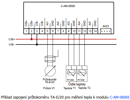
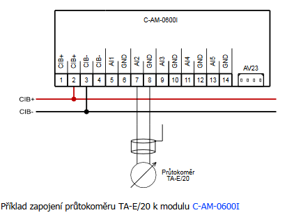
- DHW and DHW water flow measurement (cold water, hot water) - ...umption) we use a flow meter (water meter), eg TA-E / 20 with a pulse output, which is connected to the pulse inputs of the C-AM-0600I module, or to binary potential-free inputs of the basic module CP-10x8, CP-10x6. The flow meter (manufactured by...
- Heat measurement, produced and consumed heat of DHW and CH (eg heat pump) - ...duced or consumed) we use a flow meter, eg TA-E/20 with a pulse output, which we connect to the pulse inputs of the C-AM-0600I , modules, or to the binary potential-free inputs of the basic module CP-10x8 , CP-10x6 . To measure the outlet...
- Solar circuit heat measurement (max. Medium temperature up to 120 ° C) - ...he length of the supply cable approx. 110 cm. The cable is terminated with a special connector for direct connection to the C-AM-0600I module and its extension is inappropriate. Order number 223.7702.000...
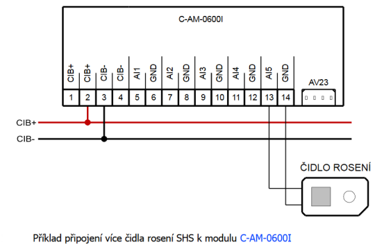
- Measuring dewing (protection against dewing on cooling ceilings, etc.) - ...around 60 s Fig. 1. An example of wiring the SHS dew sensor to the C-AM-0600I module Notes: The SHS sensor can only be connected to the AI5 input....
- S-SI-01I - ...tage of the sensor itself and the NTC 12k temperature sensor) of the modules C-IT-0200I , C-HM-xxxxM, R-HM-xxxxM, C-AM-0600I. The level of intensity (W/m 2 ) is calculated using the function in the programming environ...
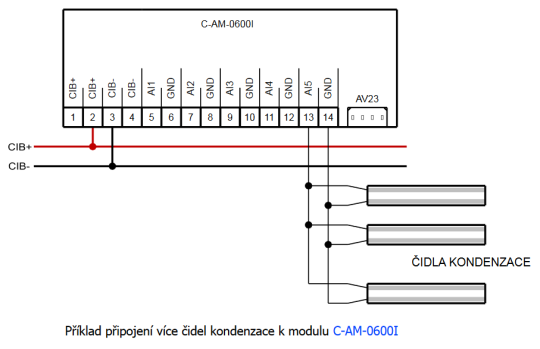
- Dew point monitoring (condensation on the distribution system of fan-coils, etc.) - ...ormation of condensation. Fig. 2. An example of the connecting several condensation sensors to the C-AM-0600I module. Notes: The condensation sensors can only be connected to the AI5 input....
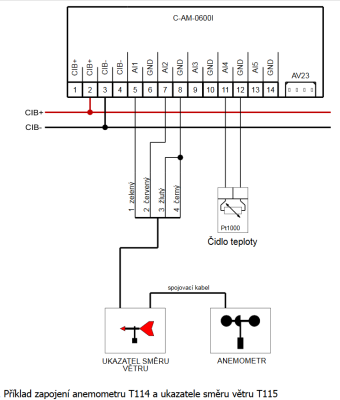
- Measuring the speed and direction of wind - ...The RJ connectors at the termination of the cable are not really necessary and can be removed. When the C-AM-0600I module is used (as in this example), its other inputs can also be utilized, e.g. for measuring the temperature of...
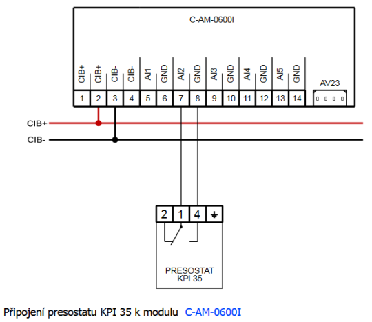
- Monitoring water pressure in the heating circuit - ...m switches the contact on and off. The output changeover contact should be connected to the binary system input, e.g. the C-AM-0600I module. Pressure switch KPI 35 The setting range...
- Metering the consumption, the Elster gas meters - ...the tamper (alarm) is connected to a conventional DI5 binary input. A number of other modules can also be used, e.g. the C-AM-0600I . The cable can be extended in the order of meters; longer distances require a shielded cable, such...
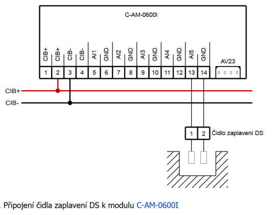
- Flood monitoring – utility room, cellar - ...the control system. The actual DS sensor should be connected to the module with a respective input for flooding, e.g. the C-AM-0600I or the C-HM-0308M. Parameters of the DS flood sensor Am...
- Flood control – the bathroom, kitchen (water leakage from appliances) - ...s in the kitchen unit, etc. The strip may be connected either to special condensation measurement inputs, e.g . the C-AM-0600I or the C-HM-0308M (these two have a high sensitivity even for liquids with low conductivity, of...
- Glass controler C-RC-0005R - Hotels, boarding houses and similar facilities can use the C-RC-0005R hotel controller. The module is equipped with several capacitive push-buttons (see the Fig.) and an OLED display. The buttons allow you to easily and intuitively change the...
- Analog input - ...B bus, there are analog inputs 0 -10 V available on modules C-IT-0200I (https://catalog.tecomat.cz/en/product/c-it-0200i) or C-AM-0600I (https://catalog.tecomat.cz/en/product/c-am-0600i). In the assortment of CIB peripheral modules are some types lik...

