


CP-2061TXN 120 61.02NNNN
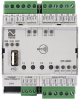
CP-2061 CPU/1core, 1xETH100/10, NFC, 2xRS-485, 4x AI/DI, 4x RO, 3x AO/PWM, 1xCIB
| DI | |
|---|---|
| DI/AI | 4x DI/AI |
| DO | 4x RO, 3x DO/PWM/AO |
| AI | |
| AO | 3x AO/PWM/DO |
| COM | 1x ETH 10/100 2x Serial channel RS-485 1x USB host 1x CIB master |
| SENSOR |
| Picture | Variant | Variant description |
|---|---|---|

|
CP-2061 |
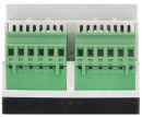
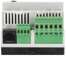
The CP-2061 is a second-generation Foxtrot base module, which is an optimal combination of a central unit with an integrated extended combination of 4 digital and analog inputs and 3 analog outputs, 3 transistor outputs or PWM, compact size occupying the width of 4 modules on a DIN rail.
Two-wire CIB Common Installation Bus® (up to 32 addressable modules). It can therefore be expanded in the same way as other base modules.
It is equipped with a total of 11 I/O:
four multi-purpose inputs, each of which can be used as either analog or binary
three analog outputs for proportional control of various connected devices.
4 independent relay outputs organized into two groups of two with their own common terminal
Communication capabilities of the basic CP-2061 module:
1x Ethernet interface 100 Mbit/s, each with up to 32 simultaneous connections (programming and general IP communication)
USB A for Flash memory, WiFi adapter (client and AP - Access point) etc.
2x serial interfaces RS-485
1x CIB interface
NFC memory
CP-2061 is equipped with a new powerful central unit (J series CPU) with memory
2 MB for the user program,
128 MB of internal disk for storing files with parallel access from LAN as a network disk,
16MB of fast RAM disk
slot for microSD card up to 1 TB
File management is provided by a journaling file system
| Order num. | TXN 120 61.02NNNN |
|---|---|
| Teco code | TXN 120 61.02NNNN |
| Categories | Foxtrot 2 - Basic modules |
| Tags | - |
| System parameters of the central unit | |
|---|---|
| Row of central unit | J |
| User program memory | 2 MB |
| Memory for user variables / including RETAIN variables | 512 kB/48 kB |
| Instruction length | 4 Byte |
| Backup of program source code in PLC | Yes, optional in Mosaic |
| On-line program change in PLC | Yes, including I / O configuration change |
| File system - Internal Drive in PLC | 128 MB, journaling file system |
| File system - RAM disk PLC | 16 MB |
| File System - USB Flash Drive | Supported |
| File system - Micro SD card | supported |
| Optional memory card slot | microSD - Card Slot (<= 1TB) |
| Cycle time per 1k of logic instructions | 0,036 ms |
| Cycle time for 1k integer operations | 0,044 ms |
| Cycle time for 1k floating point operations | 0,043 ms |
| Development environment | Mosaic v2018.2 or higher |
| Programming languages | ST, IL, LD, FBD, SFC, CFC |
| RTC - Real time circuit | Yes |
| RTC - Backup time | typ. 500 hours |
| Integrated Web server | Yes |
| Integrated Datalogger | Yes |
| Access to PLC variables via web API | Yes |
| COM - Communication - IP/Ethernet | |
| Ethernet 10/100 Mb (ETHx) | 1 |
| WLAN2 (external via USB host, optional) | 1 |
| Available system modes on ETH and WLAN | UNI, PC, PLC, PLD |
| TCP / IP protocol | Yes |
| UDP protocol | Yes |
| HTTPS protocol | Yes |
| HTTP protocol | Yes |
| WebSocket protocol | Yes |
| Protocol MODBUS/TCP | Yes |
| SMTP protocol | Yes |
| IEC 60870-5-104 protocol | Yes |
| REST API | Yes |
| COM - USB | |
| USB host interface | 1x USB-A |
| COM - Serial channels | |
| max. number of internal serial channels | 2 |
| Number of internal RS-485 serial channels | 2 |
| Max. baud rate | 1 MBd |
| Receiver sensitivity (RS-485) | min. ±200 mV |
| Signal output level (RS-485) | typ. 3 V |
| Note on cable length | The maximum length applies to twisted and shielded cable and communication speed max. 120 kBd. |
| COM - System buses | |
| CIB - Common Installation Bus (R): Installation I/O bus | 1x CIB master (400 mA) |
| CIB - Address range of one branch of the installation bus | 32 CFox I/O modules |
| DI - Parameters of binary inputs DC | |
| Number of inputs in group | 4 |
| Common wire | minus |
| Combined input type | Active / passive binary input; Active when setting the range 0-10V. Passive when setting the Pt1000, Ni1000 and KTY81-121 ranges. |
| Galvanic isolation of inputs from internal/peripheral circuits | No |
| Diagnostics | indication of energized input by LED on module panel |
| Notice | Note that the GND terminals in the 24 V DC and ANALOG OUTPUTS arrays they are connected inside the system. It is not desirable to connect the GND terminal in the ANALOG field OUTPUTS with a negative pole power supply system also inputs as it would cross the other the GND terminal has closed the loop and thereby potentially induced interfering signals. |
| DI - Parameters of binary inputs 10 V DC (group A) | |
| Number of inputs in group | 4 |
| Common wire | minus |
| Galvanic isolation of inputs from internal/peripheral circuits | No |
| Input voltage for log. 0 | max. +2V DC |
| Input voltage for log. 1 | min. +6,5 V DC , typ. +10V DC, max. +12V DC |
| Input current at log. 1 (typ.) | 3 mA typ. |
| Delay from log. 0 to log. 1 | 500 μs |
| Delay from log. 1 to log. 0 | 500 μs |
| DI - Binary input parameters potential-free contact | |
| Number of inputs in group | 4 |
| Common wire | minus |
| Input voltage for log. 0 | +3 V DC min. |
| Input voltage for log. 1 | +1 V DC max. |
| Input current at log. 1 (typ.) | -1 mA |
| Delay from log. 0 to log. 1 | 500 μs |
| Delay from log. 1 to log. 0 | 500 μs |
| HSC - Special functions of binary inputs / counters | |
| Unidirectional counter (UP) | 4x (DI0); (DI1); (DI2); (DI3) |
| PWM input (PWM) | 1x DI3 |
| HSC - Counter input parameters | |
| Special input functions | one-way counter |
| Counter: Input frequency / resolution | 1 kHz |
| Pulse width | min. 500 μs |
| Delay from log. 0 per log. 1 | 500 μs |
| Delay from log. 1 per log. 0 | 500 μs |
| Range of registers | up to 32 bits, 0 to 4 294 967 296 |
| HSC - PWM input parameters | |
| Frequency range | 10 Hz - 100 Hz |
| PWM input error | < 4% (at 100 Hz) |
| DO - Parameters of binary transistor outputs | |
| Number of transistor outputs | 3 |
| Number of output groups | 1 |
| Number of outputs in group | 3 |
| Organization of transistor outputs into groups | 3 x (PWM0-PWM2) |
| Common group conductor | GND |
| Output type | NMOS transistor with open collector. (Power load) |
| Galvanic separation from internal circuits | No |
| Diagnostics | indication of energized output by LED on module panel |
| Switching voltage | 5 - 30 V DC |
| Switching current, output load | 0,5 A max. |
| Short-term output overload capacity | 3 A |
| Switching time | typ. 9 μs |
| Opening time | typ. 13 μs |
| Alternative functions | Transistor output mode as PWM |
| RO - Parameters of binary relay outputs | |
| Parameters valid for the terminals | DO0-DO3 |
| Number of relay outputs | 4 |
| Number of output groups | 2 |
| Number of outputs in group | 2 |
| Output type | electromechanical relay, unprotected output |
| Contact type | NO - Normally Open |
| Galvanic separation from internal circuits | Yes |
| Galvanic isolation between groups | No |
| Diagnose | Alarm signaling on panel module |
| Switching current | 3 A max., 100 mA min. |
| Switching voltage | 250 V AC max., 5 V AC min., 30V DC max. |
| Short-term output overload - inrush | 4 A max. |
| Current through common clamp | 10 A max. |
| Contact closing time | typ. 10 ms |
| Contact opening time | typ. 4 ms |
| Limit values of switched resistive load | max. 3 A při 30 V DC or 230 V AC |
| Switching inductive load limits DC13 | max. 3 A at 30 V DC |
| Switching inductive load limits AC15 | max. 3 A at 230 V AC |
| Switching frequency without load | max. 300 switching / min. |
| Switching frequency with rated load | max. 20 switching / min. |
| Mechanical life | min. 5,000,000 cycles |
| Electrical life at maximum resistive load | min. 100,000 cycles |
| Electrical life at maximum load inductive DC13 | min. 100,000 cycles |
| Switching inductive load limits AC15 | min. 100,000 cycles |
| Short-circuit protection | No |
| Treatment of inductive load | External RC element, varistor (AC), diode (DC) |
| Insulation voltage between outputs and internal circuits | 3750 V AC |
| Isolation voltage between groups of outputs to each other | 1000 V AC |
| AI - Organization of analog inputs | |
| Total number of analog inputs | 4 |
| Number of inputs per group | 4 |
| Number of analog input groups | 1 |
| Organization of analog inputs into groups | 4x (DI0/AI0-DI3/AI3) |
| Input type | With common clamp |
| Common wire | Minus |
| Galvanic separation from internal circuits | No |
| Diagnostics | overload signaling in status word |
| External power supply | No |
| Digital resolution | 12 bit |
| Converter type | Approximation |
| conversion time | 20 μs |
| Operating modes | periodic input sensing |
| Filtration | low pass filter, digital comb filter 50/60 Hz |
| AI - Analog Input Ranges | |
| Voltage | 0 to 10 V / 2,579 mV |
| Voltage | 0 to 2 V / 805.9 μV |
| Input impedance in the voltage signal range | > 20 kΩ |
| Voltage input error - max. error at 25 ° C | ± 0.4% of full scale |
| Voltage input error - temperature coefficient | ± 0.03% of full scale / K |
| Voltage input error - non-linearity | ± 0.07% of full scale |
| Voltage input error - repeatability under steady state conditions | 0.05% of full scale |
| Passive sensor | Pt1000, W100 = 1,385 (-90 to +400 °C) |
| Passive sensor | Pt1000, W100 = 1,391 (-90 to +400 °C) |
| Passive sensor | Ni1000, W100 = 1,500 (–60 to +200 °C) |
| Passive sensor | Ni1000, W100 = 1.617 (-60 to +200 °C) |
| Passive sensor | Resistance transmitter 0-2 kOhm |
| Passive sensor | Resistance transmitter 0-200 kOhm |
| Passive sensor | KTY81-121; PTC thermistor (-55 to + 125 °C) |
| Passive sensor | NTC Thermistor 5k / 25 °C (–40 to + 125 °C) |
| Passive sensor | NTC Thermistor 10k / 25 °C (-40 to + 125 °C) |
| Passive sensor | NTC Thermistor 12k / 25 °C (-40 to + 125 °C) |
| Passive sensor | NTC Thermistor 15k / 25 °C (-40 to + 125 °C) |
| Passive sensor | NTC Thermistor 20k / 25 °C (-40 to + 125 °C) |
| Input impedance in signal range RTD | > 20 kΩ |
| Resistance measurement error - maximum error at 25 ° C | ±0.5% of full scale |
| Resistance measurement error - temperature coefficient | ± 0.05% of full scale / K |
| Resistance measurement error - non-linearity | ± 0.09% of full scale |
| Resistance measurement error - repeatability at steady conditions | 0.07% of full scale |
| Detection of disconnected sensor | yes, in status word, range overflow |
| AO - Analog output parameters | |
| The number of groups of analogue outputs | 1 |
| Number of outputs in group | 3 |
| Organization of outputs in groups | 3 x (AO0 - AO2) |
| Common wire of group | minus |
| Galvanic isolation from internal circuits | No |
| Galvanic isolation of outputs from each other | No |
| Output type | active voltage output |
| Max. permissible permanent overload (without damage) | ± 20 V, each terminal against AGND |
| Converter resolution | 12 bit |
| conversion time | 10 μs |
| Analog output error - maximum error at 25 ° C | ± 2% of full scale |
| Analog output error - temperature coefficient | ± 0.3% of full scale / K |
| Analog output error - linearity | ± 0.7% of full scale |
| Analog output error - repeatability under steady state conditions | ± 0.5% of full scale |
| Voltage output - voltage | 0 - 10 V |
| Voltage output - Resolution 1 LSB | 2,589 mV |
| Voltage output - maximum output current | 10 mA |
| Power supply | |
| Supply voltage, tolerances | 24 V DC, +25%, -15%, SELV |
| Maximum power input | 10 W |
| Module thermal/power loss | 12 W |
| Internal protection | Yes, PTC reversible fuse |
| CIB branch power supply - parameters of the built-in master | 1x 400 mА / 24 V DC |
| Size and weight | |
| Weight approx. | 180 g |
| Module width in multiples of M (17.5 mm) | 4M |
| Operating conditions, product standards | |
| Product standard | ČSN EN 61131-2:2008 (idt IEC 61131-2:2007) - Programmable control units |
| Protection class of electrical object | II, according to ČSN EN 61140 ed.3: 2016 (idt IEC 61140:2016) |
| IP rating (Ingress Protection) according to ČSN EN 60529: 1993 (idt IEC 529: 1989) | IP20 |
| Operating areas | Normal, acc. ČSN 33 2000-1 ed.2: 2009 (mod IEC 60354-1:2005) |
| Degree of pollution | 1, according to ČSN EN 60664-1 ed.2:2008 ( idt IEC 60664-1:2007) |
| Overvoltage category installation | II, according to EN 60664-1 ed_2: 2008 (idt IEC 60641-1: 2007) |
| Type of device | Module on DIN rail |
| Working position | Vertical |
| Type of operation (operating frequency) | Continuous |
| Ambient operating temperatures | –25 °C to +55 °C |
| Operating temperature maximum (° C) | +55°C |
| Operating temperature minimum (° C) | -25°C |
| Operating relative humidity | from 10 % up to 95 % without condensation |
| Operating atmospheric pressure | min. 70 kPa (<3,000 m above sea level) |
| Storage temperatures | –25 °C to +70 °C |
| Electromagnetic compatibility, Mechanical endurance | |
| Electromagnetic compatibility / Emission | B, according to EN 55032 ed. 2: 2017 (idt CISPR 32: 2015) |
| Emmisions - note | In premises where the use of radio and television receivers can be expected to be used a distance of 10 m from these devices may cause radio interference. In such a case, the user may be required to take appropriate action. |
| Electromagnetic compatibility / Immunity | min. as required by EN 61131-2: 2007 |
| Sinusoidal vibration endurance | 10 Hz to 57 Hz, amplitude 0,075 mm, 57 Hz to 150 Hz, acceleration 1 G (Fc test according to EN 60068-2-6: 1997 (idt IEC 68-2-6: 1995), 10 cycles per axis.) |
| Packaginng, transportation, storage | |
| Description | The module is packed in a paper box according to the internal packing instructions. The package includes the following documentation. The outer packaging is carried out according to the scope of the order and the method of transport to the transport a package bearing the transport labels and other particulars necessary for transport. Transport from the manufacturer is carried out in the manner agreed upon when ordering. Product transport the customer's own means must be carried out by covered means of transport, in the specified position label on the packaging. The box must be stowed so as to prevent spontaneous movement a damage to the outer packaging. The product must not be exposed to direct weathering during transport and storage influences. Transport is allowed at temperatures from -25 ° C to +70 ° C, relative humidity 10% up to 95% (non-condensing) and a minimum atmospheric pressure of more than 70 kPa. Storage of the product is only allowed in clean rooms without conductive dust, aggressive gases and vapors. The most suitable storage temperature is 20 ° C |
| Installation | |
| Assembly description | Switchboard mounting |
| Assembly description | The basic module is mounted vertically on the U-rail ČSN EN 50022. The installation of the assembly (basic module and peripheral modules, if applicable) is performed according to TXV 004 50. |
| Connection | |
| Connection of power and system communication | connector with 2.5 mm2 screw terminal |
| Connection of inputs / outputs | connector with screw terminal 2.5 mm2 |
| Ethernet | RJ-45 |
| Serial channels | screw-type connector 9x 1.5 mm2 |
| USB host connection | type A |
| Module operation | |
| Module configuration | The module is operated, set and diagnosed from the MOSAIC programming environment. It is also possible to connect to the PLC using a web browser on port 8080. If the PLC has an IP address set eg 192.168.134.178 (default address on port ETH1, port ETH2 has DHCP enabled), just enter the address in the form http://192.168.134.178:8080 and the web browser displays the PLC configuration pages. |
| Commissioning | The module is ready for operation after connection of the supply voltage. The MODE button is available on the module panel to display the currently set IP address of the Ethernet interface. Parameters of all interfaces are set in the Mosaic programming environment. The exact setup procedure is given in the TXV 004 50 documentation. |
| Module diagnostics | The basic diagnostic system of the module is part of its standard software. It operates from module power on and operates independently of the user. Diagnostic error states of the module and connected peripheral modules of the assembly are signaled on the module display and are available for processing by the master system. For more information, see TXV 004 50. |
| Maintenance | |
| Description | The module does not require any maintenance under general installation conditions. |
| Notice | Because the module contains semiconductor components, it is necessary to follow the principles for working with electrostatic sensitive components when handling the removed cover. It is not allowed to directly touch the printed circuit boards without protective measures !!! |
| Warranty | |
| Generally | Warranty and complaint conditions are governed by the Terms and Conditions of Teco a.s. |
| Notice | You must meet all the conditions of this documentation before turning on the system. The system must not be put into service unless it has been verified and confirmed that the machinery meets the requirements of Directive 89/392 / EEC, in so far as it applies to it. Documentation subject to change. |
EC - Declaration of Conformity
Foxtrot 2 - EC Declaration of conformity (en)
590.59 kB, (EN, RU, DE, UA)
User manuals
Foxtrot 2 - Serial communication (en)
2.25 MB, (EN, RU, DE)
Files for designers
Foxtrot 2 - library of elements in DXF and DWG formats, v. 2025/08.
21.80 MB
Foxtrot 2 - element library for SchemataCAD, v. 2025/08.
6.96 MB
HW documentation
Basic documentation CP-2061
4.38 MB, (EN)


WiFi - USB miniature adapter
TP-LINK TL-WN725N
WiFi - USB miniature adapter; 802.11b / g / n, 150 Mbps, USB 2.0
- NFC interface of the Foxtrot CP-2061 controller - The Foxtrot CP-2061 is equipped with dynamic NFC memory, which enables bidirectional data exchange between a mobile device and a PLC. Communication is carried out via an internal serial channel in MEM mode ( TXV00469 ). A data area is available th...
- CP-2061, general technical specifications of the unit - Inputs and Outputs The CP-2061 controller contains the following built-in inputs and outputs: Inputs 4× universal inputs DI0–DI3 Each input can be configured as: a binary input (10 V DC or pote...
- Identifying and Changing an Unknown IP Address on the CP-2061 - A PLC without an integrated display allows you to read and modify the ETH1 interface communication parameters using a USB flash drive . Checking the Current ETH1 Settings Procedure Turn off the supply to the PLC....
No data available.