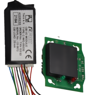
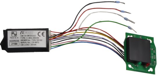
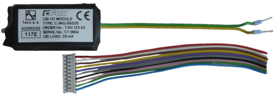
C-WG-0503STXN 133 53
C-WG-0503S; CIB, 2x AI/DI/EZS, 3x DO (NPN), 1x Wiegand/3x DI(TTL), 12VDC/60mA Stromversorgung, für Sicherheitsmelder
| DI | 3x DI 5V TTL |
|---|---|
| DI/AI | 2x DI/AI (R, binär, symmetrisch) |
| DO | |
| AI | |
| AO | Ausgangsleistung 12V / 60mA |
| COM | |
| SENSOR |
| Bild | Produktvarianten | Variantenbeschreibung |
|---|---|---|

|
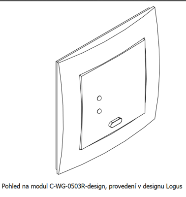
C-WG-0503S |
Das eingebaute Modul C-WG-0503S ist für den Anschluss von Geräten, die über das Wiegand-Protokoll kommunizieren, oder für den Anschluss von analogen oder binären Signalen an das System über den CIB Common Instalation Bus® und für die Erregung von LEDs, Summer usw., Ausgängen mit offene NPN-Kollektoren .
Die Eingänge DI1 bis DI3 sind als 5V TTL mit internen Pull-Up-Widerständen ausgeführt. Sie können als Binäreingänge gelesen werden oder Signale von verschiedenen Lesegeräten mit Wiegand-Protokoll auswerten, wie z. B. RFID-Kartenleser und dergleichen.
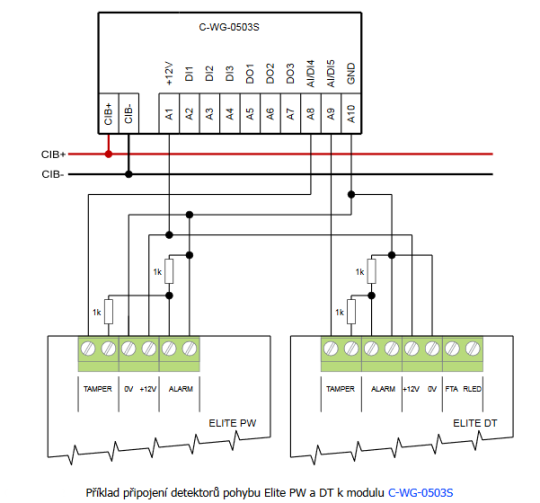
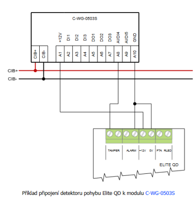
Die Eingänge DI / AI4 und DI / AI5 können als binärer potentialfreier oder symmetrischer Einbruchmelder oder als analog zur Temperatur- oder Widerstandsmessung eingestellt werden.
Das Modul enthält eine 12 V DC / 60 mA Hilfsspannungsquelle, die direkt aus dem CIB-Bus gespeist wird.
| Bestellnummer | TXN 133 53 |
|---|---|
| Teco-Code | TXN 133 53 |
| Kategorien | CFox - Eingebaute Module |
| Stichworte | - |
| COM - Systembusse | |
|---|---|
| CIB - Common Installation Bus (R): Installations-E/A-Bus | 1x CIB slave |
| DI - Organisation von Binäreingängen | |
| Gesamtzahl der binären Eingänge | 3 |
| Anzahl der binären Eingabegruppen | 1 |
| DI - Parameter der Binäreingänge DC (Gruppe A) | |
| Parameter gültig für Eingänge an den Klemmen | DI1-DI3 |
| Anzahl der Eingänge pro Gruppe | 3 |
| Gemeinsamer Draht | +12V DC |
| Kombinierter Eingabetyp | TTL 5V |
| Galvanische Trennung der Eingänge von internen/peripheren Schaltkreisen | Nein |
| DO/RO - Organisation von Binärausgängen | |
| Gesamtzahl der Binärausgänge | 3 |
| Anzahl der binären Ausgabegruppen | 1 |
| DO - Parameter der binären Transistorausgänge (Gruppe A) | |
| Parameter gültig für die Terminals | DO1-DO3 |
| Anzahl der Transistorausgänge | 3 |
| Anzahl der Ausgabegruppen | 1 |
| Anzahl der Ausgänge pro Gruppe | 3 |
| Organisation der Transistorausgänge in Gruppen | 3 (DO1-DO3) |
| Diagnostik | Nein |
| Ausgangsstrom | 30 mA |
| AI - Organisation der Analogeingänge | |
| Gesamtzahl der Analogeingänge | 2 |
| Anzahl der Eingänge pro Gruppe | 2 |
| Anzahl der analogen Eingangsgruppen | 1 |
| Organisation von Analogeingängen in Gruppen | 2x (AI1, AI2) |
| Eingabetyp | mit gemeinsamer klemme |
| Gemeinsamer Draht | Minus |
| Galvanische Trennung von internen Stromkreisen | Nein |
| Diagnostik | Überlastmeldung im Statuswort |
| Digitale Auflösung | 10 bit |
| AI - Analoge Eingangsbereiche (Gruppe A) | |
| Parameter gültig für Eingänge an den Klemmen | AI1, AI2 |
| Passive Sensor | Pt1000, W100 = 1.385 (-90 bis +320 °C) |
| Passive Sensor | Pt1000, W100 = 1.391 (-90 bis +320 °C) |
| Passive Sensor | Ni1000, W100 = 1.500 (–60 bis +200 ° C) |
| Passive Sensor | Ni1000, W100 = 1,617 (-60 bis +200 ° C) |
| Passive Sensor | Widerstandsmessumformer 0-160 kOhm |
| Passive Sensor | KTY81-121; PTC Thermistor (-55 bis + 125 °C) |
| Widerstandsmessfehler - maximaler Fehler bei 25 ° C | ± 0,5% vom Skalenendwert |
| Stromversorgung | |
| Stromversorgung über CIB - Spannung | 24/27 V DC |
| Hilfsstromversorgung - Spannung | Netzteilausgang 12 V DC; 60mA max. |
| Stromversorgung über CIB - typischer Stromverbrauch (mA) | 20 mA |
| Stromversorgung über CIB - maximale Stromaufnahme (mA) | 85 mA |
| Abmessungen und Gewicht | |
| Gewicht ca. | 7 g |
| Modulbreite | 55 mm |
| Modulhöhe | 26 mm |
| Modultiefe | 15 mm |
| Produktabmessungen (Breite x Höhe x Tiefe) | 55 × 26 × 16 mm |
| Betriebsbedingungen, Produktnormen | |
| Produktstandard | ČSN EN 60730-1 ed. 2:2001 (mod IEC 60730-1:1999) |
| Elektrische Schutzklasse | III. gemäß ČSN EN 61140: 2003 (idt IEC 61140: 2001) |
| IP-Schutzgrad gemäß ČSN EN 60529: 1993 (idt IEC 529: 1989) | IP20 |
| Arbeitsbereiche | Normal gemäß ČSN 33 2000-1: 2003 (IEC 364-1: 1992 mod) |
| Grad der Verschmutzung | 1. gemäß ČSN EN 60664-1: 2004 (mod IEC 60664-1: 1992) |
| Überspannungskategorie Installation | II, gemäß ČSN EN 60664-1: 2004 (IEC 60641: 1992 mod) |
| Art des Geräts | In der Installationsbox unter der Abdeckung |
| Arbeitshaltung | Beliebig |
| Art des Betriebs (Betriebsfrequenz) | Permanent |
| Umgebungsbetriebstemperaturen | 0 ° C bis + 70 ° C. |
| Betriebstemperatur Maximum (° C) | +55°C |
| Relative Luftfeuchtigkeit im Betrieb | 10% bis 95% ohne Kondensation |
| Lagertemperaturen | –25 ° C bis + 85 ° C. |
| Elektromagnetische Verträglichkeit, mechanische Beständigkeit | |
| Elektromagnetische Verträglichkeit / Emissionen | ČSN EN 55022 ed2:2007 (mod CISPR22:2005) |
| Elektromagnetische Verträglichkeit / Störfestigkeit | min. gemäß ČSN EN 60730-1 ed.2: 2001 |
| Widerstand gegen sinusförmige Schwingungen | 10 Hz bis 57 Hz Amplitude 0,075 mm, 57 Hz bis 150 Hz Beschleunigung 1 G (Fc-Test gemäß EN 60068-2-6: 1997 (idt IEC 68-2-6: 1995), 10 Zyklen in jeder Achse.) |
| Verpackung, Transport, Lagerung | |
| Beschreibung | Das Modul ist in einer Papierbox verpackt. Diese Dokumentation ist ebenfalls Teil des Pakets. Die Umverpackung erfolgt gemäß dem Umfang der Bestellung und der Transportart in einer Transportverpackung, die mit Etiketten und anderen für den Transport erforderlichen Daten versehen ist. Das Produkt darf während des Transports und der Lagerung keinen direkten Witterungsbedingungen ausgesetzt werden. Das Mälzen des Produkts ist nur in Reinräumen ohne leitfähigen Staub, aggressive Gase und Dämpfe zulässig. Die am besten geeignete Lagertemperatur beträgt 20 ° C. |
| Installation | |
| Montagebeschreibung | Das Modul C-DM-0001B-SL wird in beliebiger Position in der Installationsbox unter einem Deckel oder unter einem Gerät in der Box montiert. |
| Verbindung | |
| Stromversorgung und Systemkommunikation | Lose Drähte im Stecker / 0,15-0,5 mm2 |
| Verbindung - Ein- / Ausgänge | Lose Drähte im Stecker / 0,15-0,5 mm2 |
| Modulbetrieb | |
| Modulkonfiguration | Das Modul wird in der Mosaic-Entwicklungsumgebung bedient, eingestellt und diagnostiziert. |
| Wartung | |
| Beschreibung | Das Modul ist unter allgemeinen Installationsbedingungen wartungsfrei. |
| Beachten | Da das Modul Halbleiterkomponenten enthält, müssen beim Umgang mit der entfernten Abdeckung die Grundsätze für die Arbeit mit elektrostatisch empfindlichen Komponenten beachtet werden. Ohne Schutzmaßnahmen dürfen die Leiterplatten nicht direkt berührt werden !!! |
| Garantie | |
| Allgemein | Die Garantie- und Reklamationsbedingungen unterliegen den Allgemeinen Geschäftsbedingungen von Teco a.s. |
| Beachten | Sie müssen alle Bedingungen dieser Dokumentation erfüllen, bevor Sie das System einschalten. Das System darf nicht in Betrieb genommen werden, es sei denn, es wurde überprüft und bestätigt, dass die Maschinen, zu denen das System gehört, den Anforderungen der Richtlinie 89/392 / EWG entsprechen, soweit sie für sie gelten. Dokumentation freibleibend. |
HW-Dokumentation
C-WG-0503S - Basisdokumentation
851,09 kB, (DE)
Bedienungsanleitung
Peripheriemodule auf dem CIB-Common Installation Bus(R) (cs), TXV00413_01
14,01 MB
Peripheriemodule am CIB Common Installation Bus(R) (en), TXV00413_02
13,94 MB, (EN, RU, DE, UA)
Dateien für Designer
Foxtrot 2 – Bibliothek von Elementen in den Formaten DXF und DWG, Version 2025/08.
21,80 MB
Foxtrot 2 – Elementbibliothek für SchemataCAD, Version 2025/08.
6,96 MB
EC - Konformitätserklärung
Foxtrot - EC Declaration of conformity
295,20 kB, (EN, RU, DE, UA)
- C-WG-0503S - ...iegand 34 or Wiegand 42 bits and the transparent transfer 40 bits. Tab . 1. Configuration options of the C-WG-0503S module (to be set in the module software configuration) Possible configurations...
- Connecting the OP10, OP30 and OP45 sensors to the C-WG-0503S module - ...e also facilitated by the sensors OP10, OP30I, OP45 and other Honeywell products, which should be connected to the C-WG-0503S module. The module provides powering the sensor, communication between the Wiegand and the sensor, and cont...
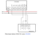
- Connecting interior motion detectors (PIR) to the C-WG-0503S module - ...g Fig. 1. An example of connecting the Elite QD motion detector to the C-WG-0503S module Notes: The connection assumes the use of double balanced loop; both the JP...
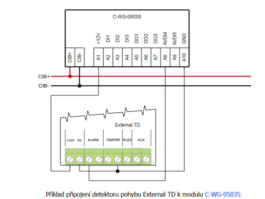
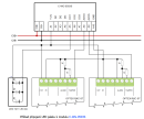
- Connecting exterior motion detectors (PIR) to the C-WG-0503S module - ... Fig. 1. An example of connecting the External TD motion detector to the C-WG-0503S module Notes: The connection assumes the use of double balanced loop; both the J...
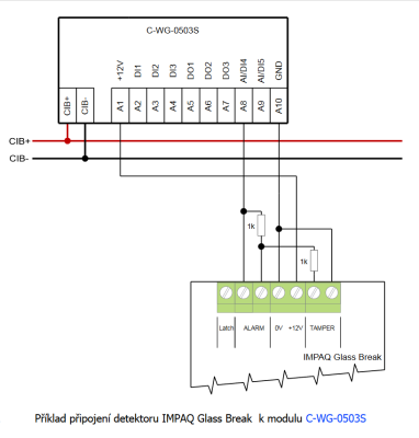
- Connecting the IMPAQ Glass Break detector to the C-WG-0503S module - ... Fig. 1. An example of connecting the IMPAQ Glass Break detector to the C-WG-0503S module Notes: The example shows the connection of the detectors loop as double b...
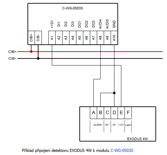
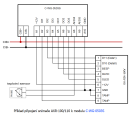
- Connecting the EXODUS fire detectors to the C-WG-0503S module - ...d ring determines the exact type). Fig. 2. An example of connecting the EXODUS 4W detector to the C-WG-0503S module Notes: The example is applicable to all variants of the EXODUS detectors (...
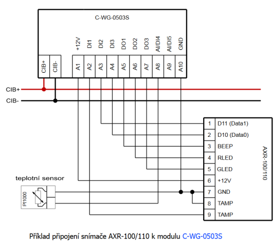
- Connecting the AXR-100/110 sensor to the C-WG-0503S module - ...3.56 MHz can be facilitated by the AXR-100/110 sensors (manufactured by EFG CZ s.r.o ), which should be connected to the C-WG-0503S module. The module provides powering the sensor, communication between the Wiegand and the sensor, and con...
- Connecting the SSA-R1000/1001 sensor to the C-WG-0503S module - ...rd readers SSA-R1000/R1100 (Samsung Format, 125 kHz) and SSA-R1001/R1101 (MIFARE, 13.56 MHz), produced by SAMSUNG, to the C-WG-0503S module is described in this chapter. The C-WG-0503S module provides communication of Wiegand with t...
- Connecting the SSA-R2000V keypad to the C-WG-0503S module - ...dentifiers) reader is best arranged by utilizing the SAMSUNG-produced SSA-R2000V keypad, which should be connected to the C-WG-0503S module. The sensor is equipped with a numeric proximity keypad and a proximity card reader in two variants: the...
- Connecting the ACM08E keypad to the C-WG-0503S module - ...with a proximity reader of cards or similar identifiers can utilize the ACM08E sensor with a keypad connected to the C-WG-0503S module. The sensor is equipped with a numeric contact keypad and a proximity card reader in accordance with the...
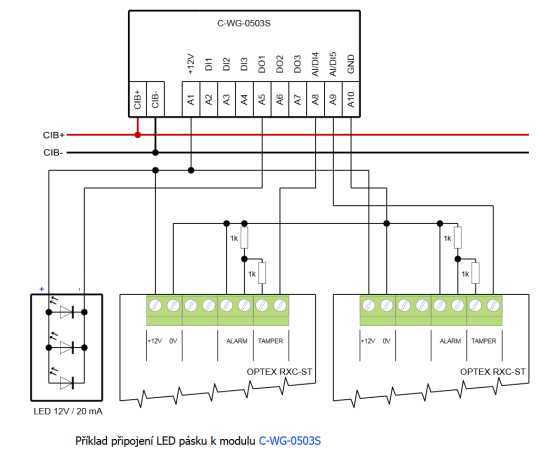
- Emergency lighting - LED strip with module C-WG-0503S - For easy-to-implement emergency lighting, we can use the C-WG-0503S , module, which will provide us with 12 VDC power supply and control (binary output) for LED strips, which can be fitted into a standard lamp. E.g. 5 cm of ordinary LED str...
- The RFID CFox card reader in the interior design, the C-WG-0503R-design - ...e.g. for connecting temperature sensors or a PIR detector, etc. The detectors can be powered from the +12 V output of the C-WG-0503S module; a maximum of 25mA is available (a maximum consumption of the powered detectors). The readin...
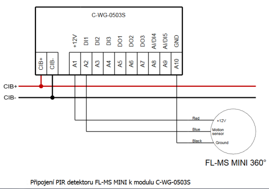
- Controlling lights using the PIR detector Vantage FL-MS - ...en collector output, so it can be easily connected to the inputs switched against signal ground, e.g. the DI1 to DI5 on the C-WG-0503S . The PIR detectors usually use NC outputs, but always with a relatively long switching time (from 500 ms to a...
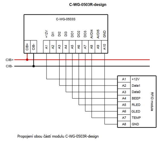
- The RFID card reader for a customized embedded design - ...ID module Notes: By default, both parts of the module (the RFID scanning part and the embedded C-WG-0503S part) are interconnected with separate approx. 100 mm long wires. The connection can be extended up to approx. 1...
- Contact-free identification, RFID sensors - ...ielded cable with a miniumum 0.35 mm 2 cross section. Sensors with the Wiegand protocol can be connected to the C-WG-0503S module or to the MX-0301 submodule....
- Emergency lighting in the house - ...d in standard lights as an additional source, e.g. a short LED strip powered from the 12 V output of CFox modules (e.g. the C-WG-0503S ) - see the following example ....
- Connecting a PIR detector with a double-balanced loop to C-IT-0200S module - ...ble, such as the C-IT-0200S module. Here you have to provide a 12 V power supply for the detectors, unlike with the C-WG-0503S module, which itself provides both 12 VDC and processing of two balanced loops, and can also be connected to a...
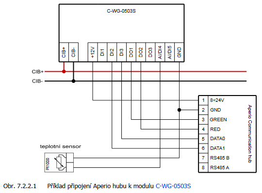
- Connecting the cylindrical insert with the integrated reader APERIO C100 - ...the wireless APERIO C100 cylinders or E100 escutcheons manufactured by Assa Abloy , there should be used the C-WG-0503S module with the Wiegand protocol. The Wiegand communication HUB should be connected to the C-WG-0503S m...
Keine Daten verfügbar.
 Deutsch
