


C-AM-0600ITXN 133 50
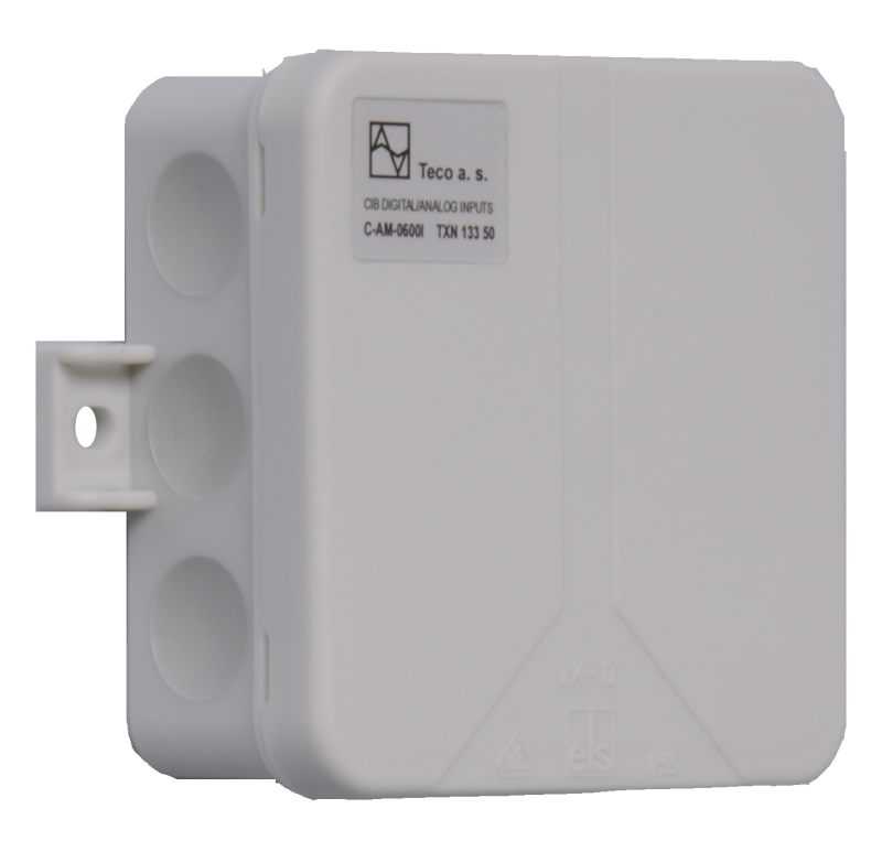
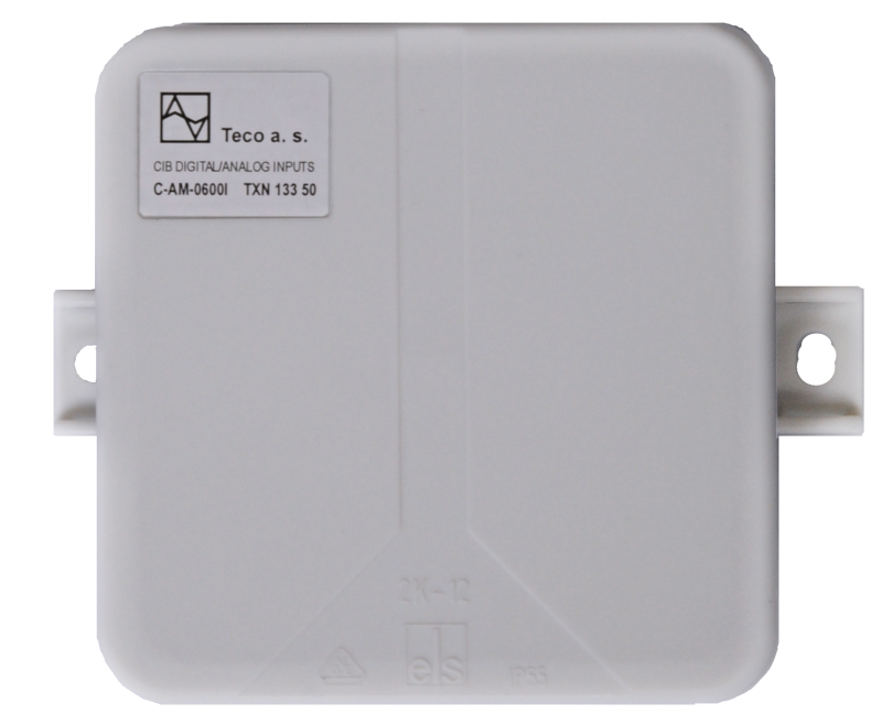
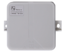
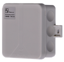
C-AM-0600I; CIB, 5xAI / DI, 1x AI Analogeingänge und Energiemessmodul, Schutzart IP55
| DI | 5x DI/Zähler |
|---|---|
| DI/AI | 5x DI/AI |
| DO | |
| AI | 1x Schnittstelle für TacoSetter Tronic Durchflussmesser |
| AO | |
| COM | 1x CIB slave |
| SENSOR | Schnittstelle für TacoSetter Tronic Durchflussmesser |
| Bild | Produktvarianten | Variantenbeschreibung |
|---|---|---|

|
C-AM-0600I |
C-AM-0600I - Modul am CIB Common Installation Bus®, enthält 5 Universaleingänge und 1 spezielle Schnittstelle zum Anschluss eines turbinenfreien TacoSetter Tronic - Durchflussmessers.
Universaleingänge können zur Messung konfiguriert werden
Universaleingänge können zur Messung konfiguriert werden
- Widerstandstemperatursensoren,
- Spannung,
- Strom
- kann als Schnittstelle zum Lesen von Impulsen von Energiezählern konfiguriert werden, z. B. Stromzählern, Gaszählern usw.
| Bestellnummer | TXN 133 50 |
|---|---|
| Teco-Code | TXN 133 50 |
| Kategorien | CFox - Außenmodule, IP54 / 65 |
| Stichworte | - |
| COM - Systembusse | |
|---|---|
| CIB - Common Installation Bus (R): Installations-E/A-Bus | 1x CIB slave |
| DI - Parameter der Binäreingänge DC (Gruppe A) | |
| Parameter gültig für Eingänge an den Klemmen | AI1-AI5 |
| Gemeinsamer Draht | GND - Modulmasse |
| Kombinierter Eingabetyp | Aktiver / passiver Binäreingang; Aktiv beim Einstellen des Bereichs 0-10V. Passiv beim Einstellen der Bereiche Pt1000, Ni1000 und KTY81-121. |
| Galvanische Trennung der Eingänge von internen/peripheren Schaltkreisen | Nein |
| Eingangsstrom bei Log. 1 (typ.) | 1,5 mA typ. |
| Verzögerung vom log. 0 zum log. 1 | 10 ms |
| Verzögerung vom log. 1 zu log. 0 | 300 ms |
| Minimale Breite des erfassten Impulses | 30 ms |
| Interner Eingangswiderstand | 64,9 kΩ |
| Warnung |
1) Der Eingang AI5 hat eine reduzierte Spannungsversorgung für den Binärzähler, die nicht dem S0-Schnittstellenstandard entspricht. 2) Digitale Eingänge haben keine eigene Konfiguration. Die Art des digitalen Eingangs kann somit unter Verwendung des entsprechenden analogen Bereichs ausgewählt werden. 3) Die Art des digitalen Eingangs wird bei der Konfiguration des Moduls in der Mosaic-Umgebung über den entsprechenden analogen Bereich eingestellt. Der aktive Digitaleingang entspricht dem Bereich 0 ÷ 10 V. Der passive Digitaleingang entspricht den Bereichen Pt1000, Ni1000, KTY81-121. |
| Impulszähler | |
| Referenzspannung (1) |
für Eingänge AI1 - AI4: Typischerweise 24 V DC (gemäß CIB-Versorgungsspannung) |
| Referenzspannung (2) |
für AI5-Eingang Typischerweise 7,4 V DC |
| Maximaler Eingangsstrom | 14 mA |
| Pulslänge | ≥ 30 ms |
| Maximale Frequenz | 20 Hz |
| Maximaler Widerstand des Schalters im geschlossenen Zustand | 800 Ω |
| AI - Organisation der Analogeingänge | |
| Anzahl der Eingänge pro Gruppe | 5 |
| Anzahl der analogen Eingangsgruppen | 1 |
| AI - Analoge Eingangsbereiche (Gruppe A) | |
| Parameter gültig für Eingänge an den Klemmen | AI1- AI5 |
| Spannung | 0-10 V |
| Spannung | 0-2 V |
| Spannung | 0 -1 V |
| Spannungseingangsfehler - max. Fehler bei 25 ° C | ± 2,0% des Skalenendwerts |
| Eingangsspannungsfehler - Temperaturkoeffizient | ± 0,1% vom Skalenendwert |
| Spannungseingangsfehler - Nichtlinearität | ± 0,1% des Skalenendwerts |
| Spannungseingangsfehler - Wiederholgenauigkeit unter stationären Bedingungen | 0,5% des Skalenendwerts |
| Strom | 0 - 20 mA |
| Strom | 4-20 mA |
| Aktueller Eingabefehler - Maximaler Fehler bei 25 ° C | ±2% des Skalenendwerts |
| Fehlerstrom-Eingang - Temperaturkoeffizient | ± 0,1% vom Skalenendwert |
| Fehlerstrom-Eingang - Nicht-Linearität | ± 0,1% vom Skalenendwert |
| Fehlerstrom-Eingang - Wiederholbarkeit bei stationären Bedingungen | 0,5% des Skalenendwerts |
| Passive Sensor | Pt1000, W100 = 1.385 (-90 bis +320 °C) |
| Passive Sensor | Pt1000, W100 = 1.391 (-90 bis +320 °C) |
| Passive Sensor | Ni1000, W100 = 1.500 (–60 bis +200 ° C) |
| Passive Sensor | Ni1000, W100 = 1,617 (-60 bis +200 ° C) |
| Passive Sensor | Widerstandsmessumformer 0-200 kOhm |
| Passiver Sensor | Widerstandsmessumformer 0-450 kOhm |
| Passive Sensor | KTY81-121; PTC Thermistor (-55 bis + 125 °C) |
| Passive Sensor | NTC Thermistor NTC 12k / 25 °C (-40 bis + 125 °C) |
| Widerstandsmessfehler - maximaler Fehler bei 25 ° C | ± 2% des Skalenendwerts |
| Widerstandsmessfehler - Temperaturkoeffizient | ± 0,1% vom Skalenendwert |
| Widerstandsmessfehler - Nichtlinearität | ± 0,1% des Skalenendwerts |
| Widerstandsmessfehler - Wiederholgenauigkeit unter stationären Bedingungen | 0,5% des Skalenendwerts |
| Durchflussmesser-Schnittstellenparameter | |
| Parameter gültig für Terminals | AV23 |
| Typ des Durchflussmessers zu verbinden | TacoSetter Tronic |
| Prinzip der Durchflussmessung | Vortex im Medium |
| Integrierte Stromversorgung für den Durchflussmesser | Ja - vom CIB-Netzteil |
| Напряжение питания расходомера | 5 V DC |
| Typischer Verbrauch von CIB | 3 mA |
| Eingang für Durchflussmesser - Eingangswiderstand | > 14 kΩ |
| Eingang für Durchflussmesser - Messbereich | 0,5 ÷ 3,5 V |
| Eingang für Durchflussmesser - Fehler beim Messen des Eingangs | 0,50 % |
| Integrierter Thermometereingang - Eingangswiderstand | > 14 kΩ |
| Integrierter Thermometereingang - Messbereich | 0,5 ÷ 3,5 V |
| Integrierter Thermometereingang - Messung des Eingangsfehlers | 0,50 % |
| Stromversorgung | |
| Versorgungsspannung, Toleranzen | 24/27 V DC vom CIB-Bus |
| Stromversorgung über CIB - typischer Stromverbrauch (mA) | 40 mA |
| Stromversorgung über CIB - maximale Stromaufnahme (mA) | 80 mA |
| Interner Schutz | Nein |
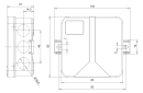
| Abmessungen und Gewicht | |
| Gewicht ca. | 70 g |
| Produktabmessungen (Breite x Höhe x Tiefe) | 85 x 85 x 37 mm |
| Betriebsbedingungen, Produktnormen | |
| Produktstandard | ČSN EN 60730-1 ed. 2:2001 (mod IEC 60730-1:1999) |
| Elektrische Schutzklasse | I, nach ČSN EN 61140 ed.3: 2016 (idt IEC 61140:2016) |
| IP-Schutzgrad gemäß ČSN EN 60529: 1993 (idt IEC 529: 1989) | IP 55 |
| Arbeitsbereiche | Normal, gemäß ČSN 33 2000-1 ed.2: 2009 (mod IEC 60354-1: 2005) |
| Grad der Verschmutzung | 1, gem. ČSN EN 60664-1 ed.2:2008 ( idt IEC 60664-1:2007) |
| Überspannungskategorie Installation | II, gemäß EN 60664-1 ed_2: 2008 (idt IEC 60641-1: 2007) |
| Art des Geräts | An der Wand |
| Arbeitshaltung | Beliebig |
| Art des Betriebs (Betriebsfrequenz) | Permanent |
| Umgebungsbetriebstemperaturen | -10 °C bis + 55 °C |
| Relative Luftfeuchtigkeit im Betrieb | 10% bis 95% ohne Kondensation |
| Betriebsatmosphärendruck | Mindest. 70 kPa (<3.000 m über dem Meeresspiegel) |
| Lagertemperaturen | -25 °C bis + 70 °C |
| Elektromagnetische Verträglichkeit, mechanische Beständigkeit | |
| Elektromagnetische Verträglichkeit / Emissionen | B, nach EN 55032 ed. 2: 2017 (idt CISPR 32: 2015) |
| Elektromagnetische Verträglichkeit / Störfestigkeit | min. gemäß ČSN EN 60730-1 ed.2: 2001 |
| Widerstand gegen sinusförmige Schwingungen | 10 Hz bis 57 Hz Amplitude 0,075 mm, 57 Hz bis 150 Hz Beschleunigung 1 G (Fc-Test gemäß EN 60068-2-6: 1997 (idt IEC 68-2-6: 1995), 10 Zyklen in jeder Achse.) |
| Verpackung, Transport, Lagerung | |
| Beschreibung | Das Modul ist in einer Papierbox verpackt. Diese Dokumentation ist ebenfalls Teil des Pakets. Die Umverpackung erfolgt gemäß dem Umfang der Bestellung und der Transportart in einer Transportverpackung, die mit Etiketten und anderen für den Transport erforderlichen Daten versehen ist. Das Produkt darf während des Transports und der Lagerung keinen direkten Witterungsbedingungen ausgesetzt werden. Das Mälzen des Produkts ist nur in Reinräumen ohne leitfähigen Staub, aggressive Gase und Dämpfe zulässig. Die am besten geeignete Lagertemperatur beträgt 20 ° C. |
| Installation | |
| Montagebeschreibung | Montáž do interiéru na stěnu |
| Verbindung | |
| Stromversorgung und Systemkommunikation | Klemmenblock mit Federklemme 1,5 mm2, push-in |
| Verbindung - Ein- / Ausgänge | Klemmenblock mit Federklemme 1,5 mm2, push-in |
| Spezifische E / A. | TacoSetter Tronic Durchflussmesser |
| Werkzeug zur Modulinstallation | (-) 3 mm flacher Schraubendreher |
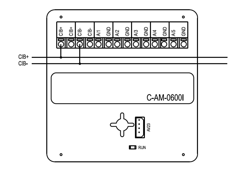
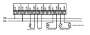
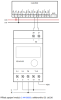
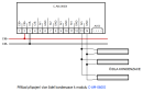
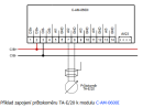
| Modulverbindung |
Das Modul ist als CIB-Busmodul implementiert, das die Kommunikation ermöglicht. Die Stromversorgung des Moduls erfolgt über eine externe Quelle. Der CIB-Bus kann eine beliebige Topologie und Verzweigung bis zu einer Entfernung von 500 m und bis zu 32 Einheiten auf einer CIB-Verzweigung aufweisen. Der CIB-Busmaster ist Foxtrot-Basiseinheit oder externer Master, z. B. das CF-1141-Modul. Weitere Informationen finden Sie im Handbuch Peripheriemodule des CIB TXV 004 13. Ein Beispiel für die Modulverbindung ist in der folgenden Abbildung dargestellt. |
| Modulbetrieb | |
| Modulkonfiguration | Das C-AM-0600I-Modul ermöglicht die Messung von Temperatur, Spannung, Strom, Widerstand und Anzahl der Impulse. Der Messbereich wird über das Modulkonfigurationsmenü in der Mosaic-Umgebung oder möglicherweise in einer anderen Konfigurations-SW ausgewählt |
| Inbetriebnahme | Das Modul wird über die MOSAIC-Programmierumgebung oder eine andere Parametrierungssoftware bedient, eingestellt und diagnostiziert. Das Modul ist nach dem Anschließen der Versorgungsspannung und des CIB-Busses betriebsbereit. Die HW-Adresse ist auf dem Etikett auf dem Modul angegeben. |
| Moduldiagnose | Die Basisdiagnose wird intern durchgeführt und das Ergebnis ist in den entsprechenden Registern der Mosaikumgebung verfügbar. |
| Wartung | |
| Beschreibung | Das Modul ist unter allgemeinen Installationsbedingungen wartungsfrei. |
| Beachten | Da das Modul Halbleiterkomponenten enthält, müssen beim Umgang mit der entfernten Abdeckung die Grundsätze für die Arbeit mit elektrostatisch empfindlichen Komponenten beachtet werden. Ohne Schutzmaßnahmen dürfen die Leiterplatten nicht direkt berührt werden !!! |
| Garantie | |
| Allgemein | Die Garantie- und Reklamationsbedingungen unterliegen den Allgemeinen Geschäftsbedingungen von Teco a.s. |
| Beachten | Sie müssen alle Bedingungen dieser Dokumentation erfüllen, bevor Sie das System einschalten. Das System darf nicht in Betrieb genommen werden, es sei denn, es wurde überprüft und bestätigt, dass die Maschinen, zu denen das System gehört, den Anforderungen der Richtlinie 89/392 / EWG entsprechen, soweit sie für sie gelten. Dokumentation freibleibend. |
HW-Dokumentation
C-AM-0600I- Grundlegende Dokumentation
229,67 kB
Bedienungsanleitung
Peripheriemodule auf dem CIB-Common Installation Bus(R) (cs), TXV00413_01
14,01 MB
Peripheriemodule am CIB Common Installation Bus(R) (en), TXV00413_02
13,94 MB, (EN, RU, DE, UA)
Dateien für Designer
Foxtrot 2 – Bibliothek von Elementen in den Formaten DXF und DWG, Version 2025/08.
21,80 MB
Foxtrot 2 – Elementbibliothek für SchemataCAD, Version 2025/08.
6,96 MB
EC - Konformitätserklärung
Foxtrot - EC Declaration of conformity
295,20 kB, (EN, RU, DE, UA)
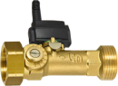
TacoSetter Tronic - Ausgleichsventil mit Durchflusssensor (1-12 l/s) und Temperatur
223.7702.000
AV23 Setter Tronic UN, 1-12 l/min, DN 20 1"x1", Balancing valve with flow and temperature sensor
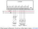
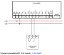
- Indirect connection of the C-AM-0600I input to the SP output via an auxiliary relay - The following figure shows an example of an indirect connection of one-command switching element to the C-AM-0600I module binary input, which provides the power control of the blocked appliances and also has information on the validity of the low ta...
- C-AM-0600I - The C-AM-0600I is a universal input module designed to measure temperature , pulse inputs, flowmeters and water meters, gas meters and electricity meters with the S0 output (class A, measuring current of approximately 10 mA). At the...
- Measurements of dewing (condensation of air humidity) - ...4.2 ). The resistive probe with the polymer layer ( Chap.11.4.1 ) can only be connected to the AI5 input of the C-AM-0600I module. The probe with the isolated electrodes ( Chap.11.4. 3 ) can be attached to the AI5 input of the...
- Metering the consumption of 1ph network, the 9901M and ED11.M electricity meter, measuring t - ...ver the 9901M electricity meter, and the ED11.M meter can also be used for some applications. The primary function of the C-AM-0600I modules is to connect the S0 electricity meters with a pulse output, in accordance with IEC 62053 it is class...
- Metering the generation and consumption of 1ph network, the ED 110 electricity meter - ...tion) can be done via the S0 output. Connecting the electricity meter with the S0 pulse output is primarily done by the C-AM-0600I modules. The SW function block enables you to obtain the total consumed energy and calculated instantaneous pow...
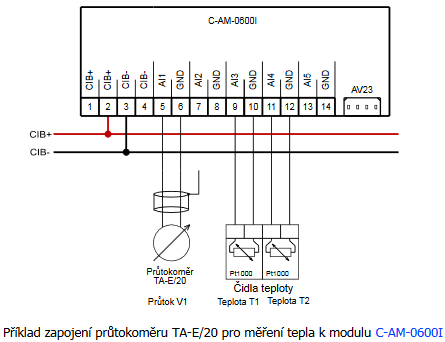
- Heat and flow measurement - ...C (the temperature sensor on the collector up to 180 °C). A suitable flowmeter is the AV23 connected to the C-AM-0600I module, which can simultaneously measure the temperature of the medium. Metering the...
- DHW and DHW water flow measurement (cold water, hot water) - ...umption) we use a flow meter (water meter), eg TA-E / 20 with a pulse output, which is connected to the pulse inputs of the C-AM-0600I module, or to binary potential-free inputs of the basic module CP-10x8, CP-10x6. The flow meter (manufactured by...
- Heat measurement, produced and consumed heat of DHW and CH (eg heat pump) - ...duced or consumed) we use a flow meter, eg TA-E/20 with a pulse output, which we connect to the pulse inputs of the C-AM-0600I , modules, or to the binary potential-free inputs of the basic module CP-10x8 , CP-10x6 . To measure the outlet...
- Solar circuit heat measurement (max. Medium temperature up to 120 ° C) - ...he length of the supply cable approx. 110 cm. The cable is terminated with a special connector for direct connection to the C-AM-0600I module and its extension is inappropriate. Order number 223.7702.000...
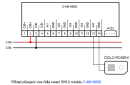
- Measuring dewing (protection against dewing on cooling ceilings, etc.) - ...around 60 s Fig. 1. An example of wiring the SHS dew sensor to the C-AM-0600I module Notes: The SHS sensor can only be connected to the AI5 input....
- S-SI-01I - ...tage of the sensor itself and the NTC 12k temperature sensor) of the modules C-IT-0200I , C-HM-xxxxM, R-HM-xxxxM, C-AM-0600I. The level of intensity (W/m 2 ) is calculated using the function in the programming environ...
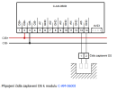
- Dew point monitoring (condensation on the distribution system of fan-coils, etc.) - ...ormation of condensation. Fig. 2. An example of the connecting several condensation sensors to the C-AM-0600I module. Notes: The condensation sensors can only be connected to the AI5 input....
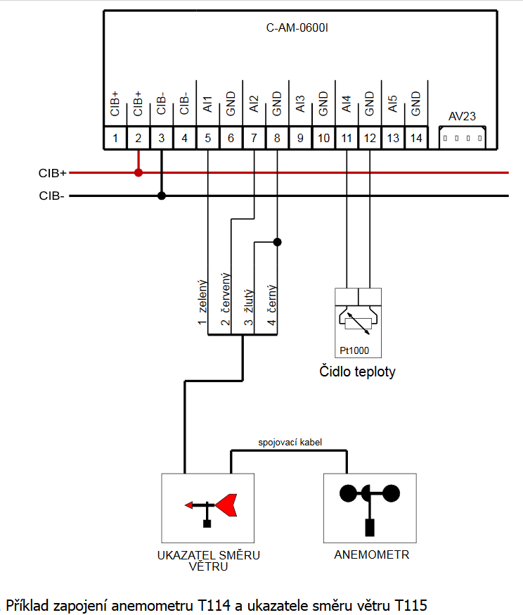
- Measuring the speed and direction of wind - ...The RJ connectors at the termination of the cable are not really necessary and can be removed. When the C-AM-0600I module is used (as in this example), its other inputs can also be utilized, e.g. for measuring the temperature of...
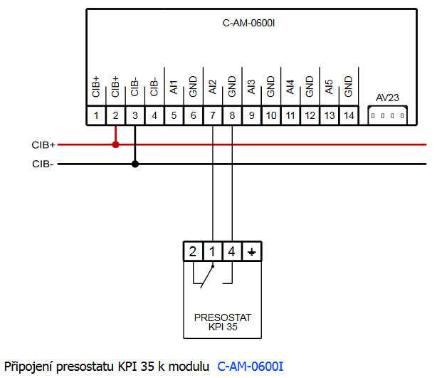
- Monitoring water pressure in the heating circuit - ...m switches the contact on and off. The output changeover contact should be connected to the binary system input, e.g. the C-AM-0600I module. Pressure switch KPI 35 The setting range...
- Metering the consumption, the Elster gas meters - ...the tamper (alarm) is connected to a conventional DI5 binary input. A number of other modules can also be used, e.g. the C-AM-0600I . The cable can be extended in the order of meters; longer distances require a shielded cable, such...
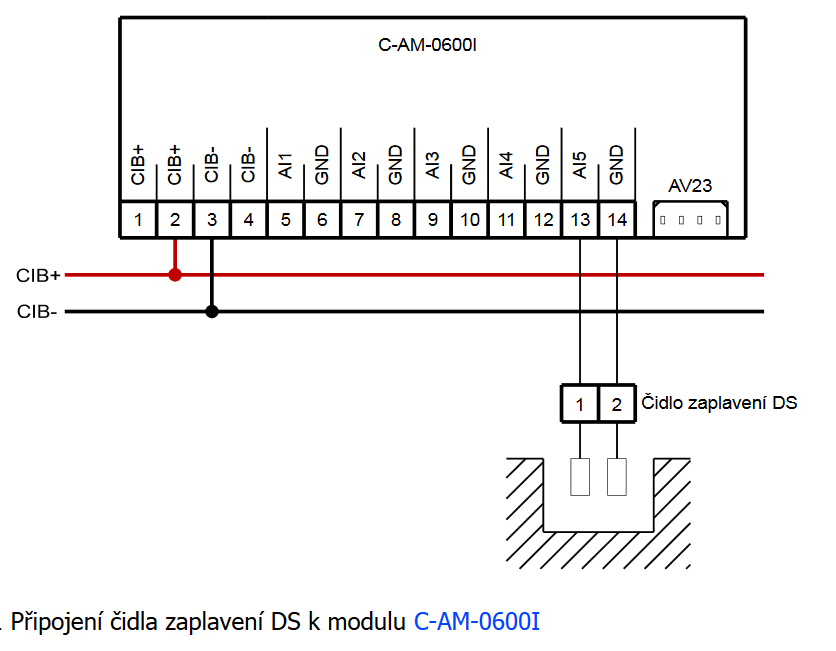
- Flood monitoring – utility room, cellar - ...the control system. The actual DS sensor should be connected to the module with a respective input for flooding, e.g. the C-AM-0600I or the C-HM-0308M. Parameters of the DS flood sensor Am...
- Flood control – the bathroom, kitchen (water leakage from appliances) - ...s in the kitchen unit, etc. The strip may be connected either to special condensation measurement inputs, e.g . the C-AM-0600I or the C-HM-0308M (these two have a high sensitivity even for liquids with low conductivity, of...
- Glass controler C-RC-0005R - Hotels, boarding houses and similar facilities can use the C-RC-0005R hotel controller. The module is equipped with several capacitive push-buttons (see the Fig.) and an OLED display. The buttons allow you to easily and intuitively change the...
- Analog input - ...B bus, there are analog inputs 0 -10 V available on modules C-IT-0200I (https://catalog.tecomat.cz/en/product/c-it-0200i) or C-AM-0600I (https://catalog.tecomat.cz/en/product/c-am-0600i). In the assortment of CIB peripheral modules are some types lik...