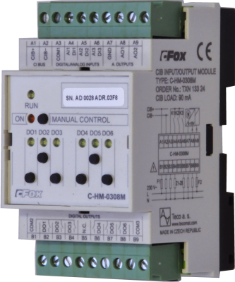
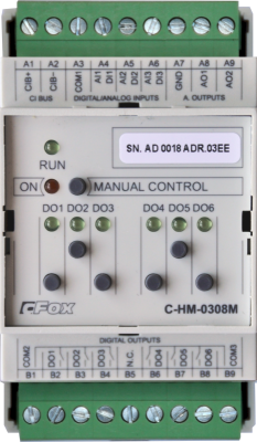
C-HM-0308MTXN 133 24
C-HM-0308M; CIB, 3x AI/DI, 2x AO, 6x RO/5A
| DI | |
|---|---|
| DI/AI | 3x DI/AI |
| DO | 6x RO |
| AI | |
| AO | 2x AO |
| COM | 1x CIB slave |
| SENSOR |
| Bild | Produktvarianten | Variantenbeschreibung |
|---|---|---|

|
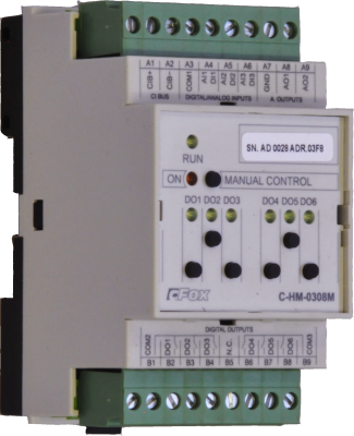
C-HM-0308M |
C-HM-0308M; CIB, 3x AI/DI, 2x AO, 6x RO/5A
| Bestellnummer | TXN 133 24 |
|---|---|
| Teco-Code | TXN 133 24 |
| Kategorien | CFox - Module auf DIN-Schiene |
| Stichworte | - |
| COM - Systembusse | |
|---|---|
| CIB - Common Installation Bus (R): Installations-E/A-Bus | 1x CIB slave |
| DI - Parameter der Binäreingänge DC (Gruppe A) | |
| Parameter gültig für Eingänge an den Klemmen | siehe AI |
| Anzahl der Eingänge pro Gruppe | 3 |
| Gemeinsamer Draht | plus |
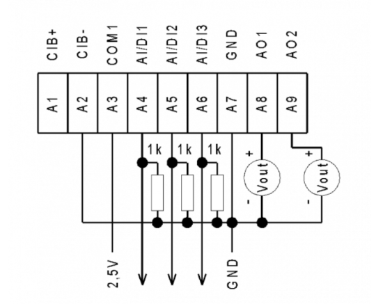
| Kombinierter Eingabetyp | DI/AI Aktiv, zum Erfassen Potentialfreier Kontakte und zum Messen von Widerstandssensoren |
| Galvanische Trennung der Eingänge von internen/peripheren Schaltkreisen | Nein |
| Diagnostik | Signalisierung von angeregten Eingaben in Mosaic |
| Impulseingangsüberlastfähigkeit | max. 30 V (t < 10 ms) |
| Eingangsstrom bei Log. 1 (typ.) | 2,5 mA typ. |
| Verzögerung vom log. 0 zum log. 1 | 500 μs |
| Verzögerung vom log. 1 zu log. 0 | 500 μs |
| Minimale Breite des erfassten Impulses | 500 μs |
| RO - Parameter der binären Relaisausgänge (Gruppe A) | |
| Anzahl der Relaisausgänge | 6 |
| Anzahl der Ausgabegruppen | 2 |
| Anzahl der Ausgänge in Gruppe | 3 |
| Ausgangstyp | elektromechanisches Relais, ungeschützter Ausgang |
| Kontakttyp | NO - (Normally Open) Umschalten |
| Diagnose | Alarmsignalisierung ein Panel-Modul |
| Schaltspannung | 250 V AC max., 5 V AC min., 30V DC max. |
| Strom durch gemeinsame Klemme | 10 A max. |
| Kontaktschlusszeit | typ. 15 ms |
| Grenzwerte der geschalteten ohmschen Last | Max. 3A bei 30 V DC oder 230 V AC |
| AI - Organisation der Analogeingänge | |
| Gesamtzahl der Analogeingänge | 3 |
| Anzahl der Eingänge pro Gruppe | 3 |
| Anzahl der analogen Eingangsgruppen | 1 |
| Galvanische Trennung von internen Stromkreisen | Nein |
| Externe Stromversorgung | Nein |
| Digitale Auflösung | 12 bit |
| Konvertertyp | Annäherung |
| Wandlungszeit | 20 μs |
| AI - Analoge Eingangsbereiche (Gruppe A) | |
| Spannung | 0 bis 2 V / 805,9 μV |
| Spannung | 0 -1 V |
| Eingangserkennung öffnen | Nein |
| Passive Sensor | Pt1000, W100 = 1.385 (-90 bis +320 °C) |
| Passive Sensor | Pt1000, W100 = 1.391 (-90 bis +320 °C) |
| Passive Sensor | Ni1000, W100 = 1.500 (–60 bis +200 ° C) |
| Passive Sensor | Ni1000, W100 = 1,617 (-60 bis +200 ° C) |
| Passiver Sensor | Widerstandsmessumformer 0-600 kOhm |
| Passiver Sensor | Widerstandsmessumformer 0-6 MOhm |
| Passive Sensor | KTY81-121; PTC Thermistor (-55 bis + 125 °C) |
| Passive Sensor | NTC Thermistor NTC 12k / 25 °C (-40 bis + 125 °C) |
| AO - Parameter der analogen Ausgänge | |
| Anzahl der Analogausgangsgruppen | 1 |
| Gemeinsame Drahtgruppen | GND-Anschluss |
| Galvanische Trennung von internen Stromkreisen | Nein |
| Ausgabetyp | aktiver Spannungsausgang |
| Stromversorgung | |
| Nennversorgungsspannung (V) | 24 V DC |
| Maximaler Stromverbrauch | 2 W |
| Wärme-/Leistungsverlust des Moduls | 2,1 W |
| Stromversorgung über CIB - maximale Stromaufnahme (mA) | 90 mA |
| Galvanische Trennung der Stromversorgung von internen Schaltkreisen | Nein |
| Interner Schutz | Nein |
| Abmessungen und Gewicht | |
| Produktabmessungen (Breite x Höhe x Tiefe) | 52 x 90 x 58 mm |
| Modulbreite | 52 mm |
| Modulhöhe | 90 mm |
| Modultiefe | 58 mm |
| Betriebsbedingungen, Produktnormen | |
| Produktstandard | ČSN EN 60730-1 ed. 2:2001 (mod IEC 60730-1:1999) |
| Elektrische Schutzklasse | I, nach ČSN EN 61140 ed.3: 2016 (idt IEC 61140:2016) |
| IP-Schutzgrad gemäß ČSN EN 60529: 1993 (idt IEC 529: 1989) | IP20 |
| Grad der Verschmutzung | 1, gem. ČSN EN 60664-1 ed.2:2008 ( idt IEC 60664-1:2007) |
| Überspannungskategorie Installation | II, gemäß EN 60664-1 ed_2: 2008 (idt IEC 60641-1: 2007) |
| Art des Geräts | Modul auf DIN-Schiene |
| Arbeitshaltung | Vertikal |
| Art des Betriebs (Betriebsfrequenz) | Permanent |
| Umgebungsbetriebstemperaturen | -20 °C bis + 55 °C |
| Relative Luftfeuchtigkeit im Betrieb | 10% bis 95% ohne Kondensation |
| Betriebsatmosphärendruck | Mindest. 70 kPa (<3.000 m über dem Meeresspiegel) |
| Lagertemperaturen | -25 °C bis + 70 °C |
| Elektromagnetische Verträglichkeit, mechanische Beständigkeit | |
| Elektromagnetische Verträglichkeit / Emissionen | B, nach EN 55032 ed. 2: 2017 (idt CISPR 32: 2015) |
| Emissionen - Hinweis | Dieses Produkt kann in Bereichen, in denen Radio- und Fernsehempfänger voraussichtlich weniger als 10 m entfernt sind, Funkstörungen verursachen. In diesem Fall kann der Benutzer aufgefordert werden, geeignete Maßnahmen zu ergreifen |
| Elektromagnetische Verträglichkeit / Störfestigkeit | min. gemäß ČSN EN 60730-1 ed.2: 2001 |
| Widerstand gegen sinusförmige Schwingungen | 10 Hz bis 57 Hz Amplitude 0,075 mm, 57 Hz bis 150 Hz Beschleunigung 1 G (Fc-Test gemäß EN 60068-2-6: 1997 (idt IEC 68-2-6: 1995), 10 Zyklen in jeder Achse.) |
| Verpackung, Transport, Lagerung | |
| Beschreibung | Das Modul ist in einer Papierbox verpackt. Diese Dokumentation ist ebenfalls Teil des Pakets. Die Umverpackung erfolgt gemäß dem Umfang der Bestellung und der Transportart in einer Transportverpackung, die mit Etiketten und anderen für den Transport erforderlichen Daten versehen ist. Das Produkt darf während des Transports und der Lagerung keinen direkten Witterungsbedingungen ausgesetzt werden. Das Mälzen des Produkts ist nur in Reinräumen ohne leitfähigen Staub, aggressive Gase und Dämpfe zulässig. Die am besten geeignete Lagertemperatur beträgt 20 ° C. |
| Installation | |
| Montagebeschreibung | Das Hotelmodul C-HM-0308M ist vertikal auf der U-Schiene ČSN EN 50022 montiert. Die Installation des Sets (Basismodul und möglicherweise Peripheriemodule) erfolgt gemäß TXV 004 13. |
| Verbindung | |
| Verbindungsbeschreibung |
Hotelmodule werden standardmäßig auf einem Zweidraht-CIB-Bus implementiert, der die Kommunikation und Stromversorgung des gesamten Moduls gewährleistet. Der CIB-Bus kann eine beliebige Topologie und Verzweigung bis zu einer Entfernung von 500 m und bis zu 32 Einheiten auf einer CIB-Verzweigung aufweisen. Der CIB-Bus-Master ist die FOXTROT-Basiseinheit oder das MI2-02M-Modul. Weitere Informationen finden Sie im Handbuch Peripheriemodule des CIB TXV 004 13. |
| Stromversorgung und Systemkommunikation | Stecker mit 2,5 mm2 Schraubklemme |
| Verbindung - Ein- / Ausgänge | Stecker mit Schraubklemme 2,5 mm2 |
| Modulbetrieb | |
| Modulkonfiguration | Das Modul wird in der Mosaic-Entwicklungsumgebung bedient, eingestellt und diagnostiziert. |
| Inbetriebnahme | Das Modul ist nach dem Anschließen der Versorgungsspannung betriebsbereit. Die MODE-Taste ist auf dem Modulfeld verfügbar, um die aktuell eingestellte Ethernet-IP-Adresse anzuzeigen. Die Parameter aller Schnittstellen werden in der Mosaic-Entwicklungsumgebung festgelegt. |
| Wartung | |
| Beschreibung | Das Modul ist unter allgemeinen Installationsbedingungen wartungsfrei. Die Arbeiten, bei denen ein Teil des Moduls zerlegt werden muss, müssen immer bei abgeschalteter Versorgungsspannung durchgeführt werden. |
| Beachten | Da das Modul Halbleiterkomponenten enthält, müssen beim Umgang mit der entfernten Abdeckung die Grundsätze für die Arbeit mit elektrostatisch empfindlichen Komponenten beachtet werden. Ohne Schutzmaßnahmen dürfen die Leiterplatten nicht direkt berührt werden !!! |
| Garantie | |
| Allgemein | Die Garantie- und Reklamationsbedingungen unterliegen den Allgemeinen Geschäftsbedingungen von Teco a.s. |
| Beachten | Sie müssen alle Bedingungen dieser Dokumentation erfüllen, bevor Sie das System einschalten. Das System darf nicht in Betrieb genommen werden, es sei denn, es wurde überprüft und bestätigt, dass die Maschine die Anforderungen der Richtlinie 2006/42 / EG für Maschinen erfüllt, soweit dies für sie gilt. |
HW-Dokumentation
C-HM-0308M - Basisdokumentation
1,42 MB, (DE)
Bedienungsanleitung
Peripheriemodule auf dem CIB-Common Installation Bus(R) (cs), TXV00413_01
14,01 MB
Peripheriemodule am CIB Common Installation Bus(R) (en), TXV00413_02
13,94 MB, (EN, RU, DE, UA)
Dateien für Designer
Foxtrot 2 – Bibliothek von Elementen in den Formaten DXF und DWG, Version 2025/08.
21,80 MB
Foxtrot 2 – Elementbibliothek für SchemataCAD, Version 2025/08.
6,96 MB
EC - Konformitätserklärung
Foxtrot - EC Declaration of conformity
295,20 kB, (EN, RU, DE, UA)
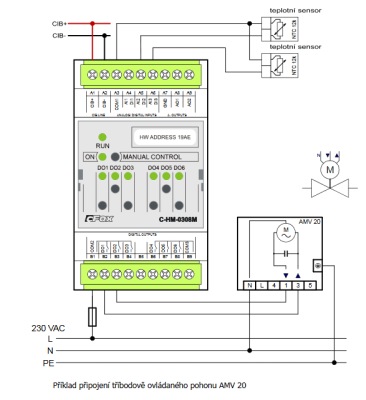
- C-HM-0308M - ...minute. This must be taken into consideration when using relay outputs. Fig. 1 The basic connection of the C-HM-0308M module Notes: The analogue inputs AI1 to AI3 are intended for connecting the temperature sensors...
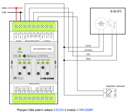
- Measuring solar radiation by the S-SI-01I sensor with the C-HM-0308M module - ...solar radiation can be done by the S-SI-01I module, which should be connected to the analogue inputs of the modules C-HM-0308M , C(R)-HM-1113M or C(R)-HM-1121M. The solar radiation sensor uses for its own measurement of intensity a mon...
- Power dissipation of modules for calculation of switchboard heating - ...for measuring transformers with 100mA output C-EM-0401M-S 4,0 W TXN 133 24 C-HM-0308M; CIB, 3x AI/DI, 2x AO, 6x RO/5A C-HM-0308M 2,1 W TXN 133 45 C-DM...
- Measurement of soil moisture (irrigation systems) - ...ation and as per the documentation [ 11 ] . Fig. 1. Wiring the soil moisture sensor to the C-HM-0308M module. Notes: The standard length of the supply cable is 2m. Other l...
- The separate temperature sensor S-TS-01R, connected to the AI of the system - ...ith an appropriate range, e.g. the AI1 to AI4 inputs of the C-IB-1800M module , the AI1 to AI3 inputs of the modules C-HM-0308M , C (R) -HM-1113M and C (R) -HM-1121M . Fig. 1. An example of connecting the S-T...
- Measurements of dewing (condensation of air humidity) - ...ap.11.4. 3 ) can be attached to the AI5 input of the C-AM-0600I module, or to the inputs AI1 to AI3 of the modules C-HM-0308M , HM-C-1113M and C-HM-1121M . In order for the dew sensor to function properly, it must hav...
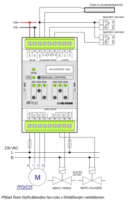
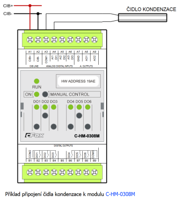
- Dew point monitoring (condensation on the distribution system of fan-coils, etc.) - ...raps to the bottom part of the piping. Fig. 1. An example of connecting the condensation sensor to the C-HM-0308M module. Notes: The condensation sensor can be connected to any input of the module (AI1...
- Point level monitoring of water level in the well or in a tank - ...done by conductive probes (e.g. the CNP-18) connected to analogue inputs intended measuring condensation, e.g. the C-HM-0308M . Monitoring the minimum and maximum levels requires three probes with sufficient lengths of stems to allow eval...
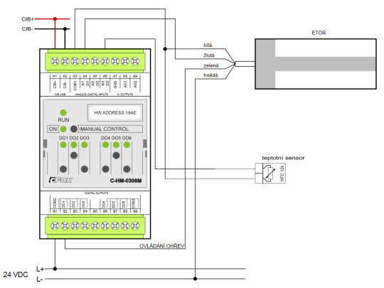
- Defrosting outdoor spaces, the ESF 524 001 sensor - ...les can be controlled by any relay output of the control system (according to the switching power). The connection to the C-HM-0308M module is shown in the following figure. Fig. .1 A wiring example – defrosting of sm...
- Defrosting gutters, the ESD 524 03 sensor - ...an appropriate range (the humidity sensor is connected to the input for condensation measurement). The connection to the C-HM-0308M module is shown in the following figure. Fig. 1. A wiring diagram – defrosting gutte...
- Flood monitoring – utility room, cellar - ...actual DS sensor should be connected to the module with a respective input for flooding, e.g. the C-AM-0600I or the C-HM-0308M. Parameters of the DS flood sensor Ambient temperature...
- Control of the 24 V TORO valves for the irrigation systems - ...alves by relay outputs of the CP-1006 basic module. The relay outputs of other modules can be used in the same way, e.g. the C-HM-0308M, etc. Thanks to the small initial and trickle currents, relay outputs fitted with a 5 A and 16 A contacts can be u...
- Flood control – the bathroom, kitchen (water leakage from appliances) - .... The strip may be connected either to special condensation measurement inputs, e.g . the C-AM-0600I or the C-HM-0308M (these two have a high sensitivity even for liquids with low conductivity, of a very short pieces of the...
- The 5A relays, the Foxtrot basic modules and the peripheral CFox modules - These relays are fitted in e.g. the Foxtrot basic modules (CP-1005, CP1006, etc.), the peripheral modules ( C-HM-0308M , C-IR-0202S ) and others (see information on the individual modules ). The parameters of t...
- Water underfloor heating - ...m can be used for the control function. The following figure demonstrates the control of 6 actuators in the manifold. The C-HM-0308M module used in the example can be mounted directly in the manifold. For detailed information on suitable...
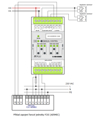
- Fan-coils - control - ...ition heating drives and cooling, with an example of connection of a condensation sensor and two temperature sensors. The C-HM-0308M module used in this case offers a possibility of controlling e.g. analogue-controlled drives, or controlling th...
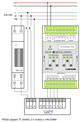
- Connecting the CARRIER 30AWH__H heat pump - ...connection, see the heat pump instruction manual. The following figure shows an example of possible connection to the C-HM-0308M module (heat pump control) and measuring the heat pump current by the ED11.M electricity meter ....
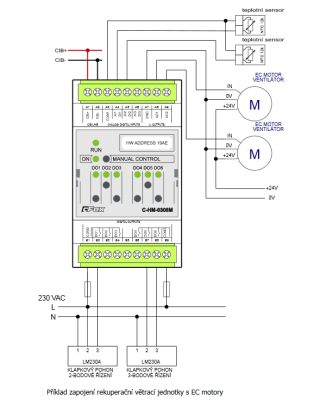
- Ventilation and recuperation units - ...discreet speed control of 230 V motor revolutions relay modules, e.g. C-HM-0308M Continuous regulation of 230 V asynchronous motors, built-in version...
- Switching of LED lighting, light bulbs, fluorescent lamps, etc. - .... We can use any relay outputs of the Foxtrot system for switching classic light bulbs . E.g. relay outputs of the C-HM-0308M module are equipped with a relay with 5A contact, continuous switching current 3A, so we can switch up to 600W wi...
- Fan speed control, heat recovery units - The figure shows an example of controlling heat recovery units with two fans with EC motors, an actuator and a valve, up to three temperature sensors, and all connected to the C-HM-0308 module. Fig. 1. An example of connecting a heat rec...
- Electric underfloor heating - The direct electric underfloor heating can be designed similarly to hot water underfloor heating. The heating elements are in this case electric heating cables (the installation is similar to hot water systems), heating mats (a more convenient inst...
Keine Daten verfügbar.

