 English


C-WG-0503STXN 133 53
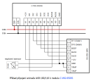
C-WG-0503S; CIB, 2x AI/DI/EZS, 3x DO (NPN), 1x Wiegand/3x DI(TTL), 12VDC/60mA power supply, for security detectors
| DI | |
|---|---|
| DO | |
| AI | 2x AI / DI (R, binary, balanced) |
| AO | Power output 12V / 60mA |
| COM | |
| SENSOR |
| Picture | Variant | Variant description |
|---|---|---|

|
C-WG-0503S |
Built-in module C-WG-0503S is designed for connection of devices communicating via Wiegand protocol, or for connection of analog or binary signals to the system via CIB Common Instalation Bus® and for excitation of LEDs, buzzer, etc., outputs with open NPN collectors .
Inputs DI1 to DI3 are designed as 5V TTL with internal pull up resistors. They can be read as binary inputs or evaluate signals from various readers with the Wiegand protocol, such as RFID card readers and the like.
Inputs DI / AI4 and DI / AI5 can be set as binary potential-free or balanced burglar alarm or as analog for temperature or resistance measurement.
The module contains a 12 V DC / 60 mA auxiliary voltage source, which is supplied directly from the CIB bus.
| Order num. | TXN 133 53 |
|---|---|
| Teco code | TXN 133 53 |
| Categories | CFox - Built-in modules |
| Tags | - |
| COM - System buses | |
|---|---|
| CIB - Common Installation Bus (R): Installation I/O bus | 1x CIB slave |
| DI - Organization of binary inputs | |
| Total number of binary inputs | 3 |
| Number of groups of binary inputs | 1 |
| DI - Parameters of binary inputs DC (group A) | |
| Parameters valid for inputs on the terminals | DI1-DI3 |
| Number of inputs in group | 3 |
| Common wire | +12V DC |
| Combined input type | TTL 5V |
| Galvanic isolation of inputs from internal/peripheral circuits | No |
| DO/RO - Organization of binary outputs | |
| Total number of binary outputs | 3 |
| Number of binary output groups | 1 |
| DO - Parameters of binary transistor outputs (group A) | |
| Parameters valid for the terminals | DO1-DO3 |
| Number of transistor outputs | 3 |
| Number of output groups | 1 |
| Number of outputs in group | 3 |
| Organization of transistor outputs into groups | 3 (DO1-DO3) |
| Diagnostics | No |
| Output current | 30 mA |
| AI - Organization of analog inputs | |
| Total number of analog inputs | 2 |
| Number of inputs per group | 2 |
| Number of analog input groups | 1 |
| Organization of analog inputs into groups | 2x (AI1, AI2) |
| Input type | With common clamp |
| Common wire | Minus |
| Galvanic separation from internal circuits | No |
| Diagnostics | overload signaling in status word |
| Digital resolution | 10 bit |
| AI - Analog Input Ranges (Group A) | |
| Parameters valid for inputs on the terminals | AI1, AI2 |
| Passive sensor | Pt1000, W100 = 1,385 (-90 to +400 ° C) |
| Passive sensor | Pt1000, W100 = 1,391 (-90 to +400 ° C) |
| Passive sensor | Ni1000, W100 = 1,500 (–60 to +200 ° C) |
| Passive sensor | Ni1000, W100 = 1.617 (-60 to +200 ° C) |
| Passive sensor | Resistance transmitter 0-160 kOhm |
| Passive sensor | KTY81-121; PTC thermistor (-55 to + 125 °C) |
| Resistance measurement error - maximum error at 25 ° C | ± 0.5% of full scale |
| Power supply | |
| Power supply from CIB - voltage | 24/27 V DC |
| Auxiliary power supply - voltage | Power supply output 12 V DC; 60 mA max. |
| Power supply from CIB - typical current consumption (mA) | 20 mA |
| Power supply from CIB - maximum current consumption (mA) | 85 mA |
| Size and weight | |
| Weight approx. | 7 g |
| Module width | 55 mm |
| Module height | 26 mm |
| Module depth | 15 mm |
| Product dimensions (width x height x depth) | 55 × 26 × 16 mm |
| Operating conditions, product standards | |
| Product standard | ČSN EN 60730-1 ed. 2:2001 (mod IEC 60730-1:1999) |
| Protection class of electrical object | III, according to ČSN EN 61140: 2003 (idt IEC 61140: 2001) |
| IP rating (Ingress Protection) according to ČSN EN 60529: 1993 (idt IEC 529: 1989) | IP20 |
| Operating areas | Normal according to ČSN 33 2000-1: 2003 (IEC 364-1: 1992 mod) |
| Degree of pollution | 1, according to ČSN EN 60664-1: 2004 (mod IEC 60664-1: 1992) |
| Overvoltage category installation | II, acc. ČSN EN 60664-1:2004 (mod IEC 606641:1992) |
| Type of device | In the installation box, under the cover |
| Working position | Any |
| Type of operation (operating frequency) | Continuous |
| Ambient operating temperatures | 0 ° C to + 70 ° C |
| Operating temperature maximum (° C) | +55°C |
| Operating temperature minimum (° C) | 0°C |
| Operating relative humidity | from 10 % up to 95 % without condensation |
| Storage temperatures | –25 ° C to + 85 ° C |
| Electromagnetic compatibility, Mechanical endurance | |
| Electromagnetic compatibility / Emission | ČSN EN 55022 ed2:2007 (mod CISPR22:2005) |
| Electromagnetic compatibility / Immunity | min. according to ČSN EN 60730-1 ed.2: 2001 |
| Sinusoidal vibration endurance | 10 Hz to 57 Hz, amplitude 0,075 mm, 57 Hz to 150 Hz, acceleration 1 G (Fc test according to EN 60068-2-6: 1997 (idt IEC 68-2-6: 1995), 10 cycles per axis.) |
| Packaginng, transportation, storage | |
| Description | The module is packed in a paper box. This documentation is also part of the package. The outer packaging is carried out according to the scope of the order and the method of transport in a transport package provided with labels and other data necessary for transport. The product must not be exposed to direct weather conditions during transport and storage. Malting of the product is only allowed in clean rooms without conductive dust, aggressive gases and vapors. The most suitable storage temperature is 20 ° C |
| Installation | |
| Assembly description | The module C-DM-0001B-SL is mounted in arbitrary positioninto instalation box under a lid or under device located in box. |
| Connection | |
| Connection of power and system communication | Loose wires in the connector / 0.15-0.5 mm2 |
| Connection of inputs / outputs | Loose wires in the connector / 0.15-0.5 mm2 |
| Module operation | |
| Module configuration | The module is operated, set up and diagnosed from the Mosaic development environment. |
| Maintenance | |
| Description | The module does not require any maintenance under general installation conditions. |
| Notice | Because the module contains semiconductor components, it is necessary to follow the principles for working with electrostatic sensitive components when handling the removed cover. It is not allowed to directly touch the printed circuit boards without protective measures !!! |
| Warranty | |
| Generally | Warranty and complaint conditions are governed by the Terms and Conditions of Teco a.s. |
| Notice | You must meet all the conditions of this documentation before turning on the system. The system must not be put into service unless it has been verified and confirmed that the machinery meets the requirements of Directive 89/392 / EEC, in so far as it applies to it. Documentation subject to change. |
HW documentation
C-WG-0503S - Basic documentation
849.34 kB, (EN)
User manuals
Peripheral modules on the CIB Common Installation Bus(R) (en), TXV00413_02
13.94 MB, (EN, RU, DE, UA)
Files for designers
Foxtrot 2 - library of elements in DXF and DWG formats, v. 2024/01.
20.49 MB
Foxtrot 2 - element library for SchemataCAD, v. 2024/01
6.79 MB
EC - Declaration of Conformity
Foxtrot - EC Declaration of conformity
295.20 kB, (EN, RU, DE, UA)
- C-WG-0503S - ...iegand 34 or Wiegand 42 bits and the transparent transfer 40 bits. Tab . 1. Configuration options of the C-WG-0503S module (to be set in the module software configuration) Possible configurations...
- Connecting the OP10, OP30 and OP45 sensors to the C-WG-0503S module - ...e also facilitated by the sensors OP10, OP30I, OP45 and other Honeywell products, which should be connected to the C-WG-0503S module. The module provides powering the sensor, communication between the Wiegand and the sensor, and cont...
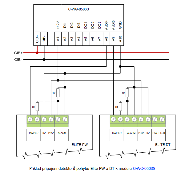
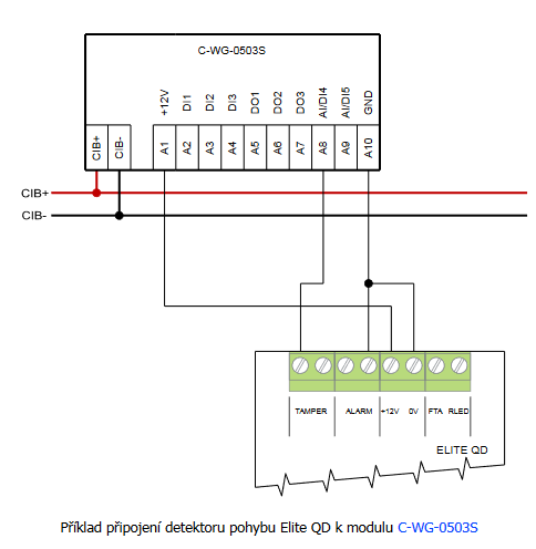
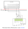
- Connecting interior motion detectors (PIR) to the C-WG-0503S module - ...g Fig. 1. An example of connecting the Elite QD motion detector to the C-WG-0503S module Notes: The connection assumes the use of double balanced loop; both the JP...
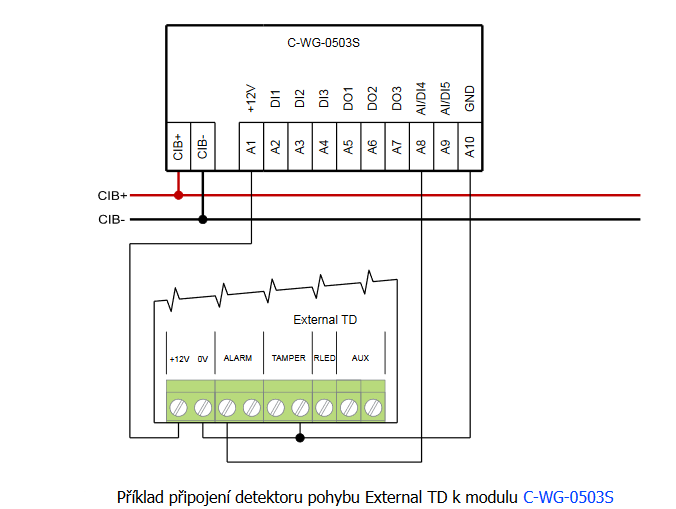
- Connecting exterior motion detectors (PIR) to the C-WG-0503S module - ... Fig. 1. An example of connecting the External TD motion detector to the C-WG-0503S module Notes: The connection assumes the use of double balanced loop; both the J...
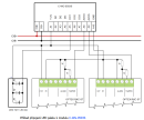
- Connecting the IMPAQ Glass Break detector to the C-WG-0503S module - ... Fig. 1. An example of connecting the IMPAQ Glass Break detector to the C-WG-0503S module Notes: The example shows the connection of the detectors loop as double b...
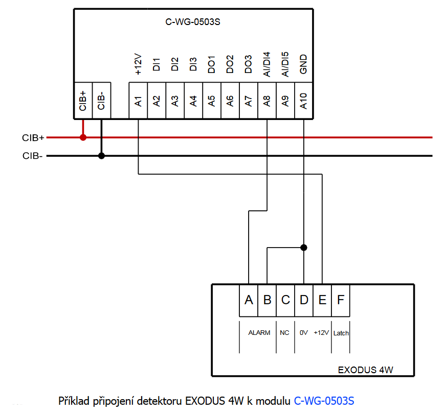
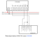
- Connecting the EXODUS fire detectors to the C-WG-0503S module - ...d ring determines the exact type). Fig. 2. An example of connecting the EXODUS 4W detector to the C-WG-0503S module Notes: The example is applicable to all variants of the EXODUS detectors (...
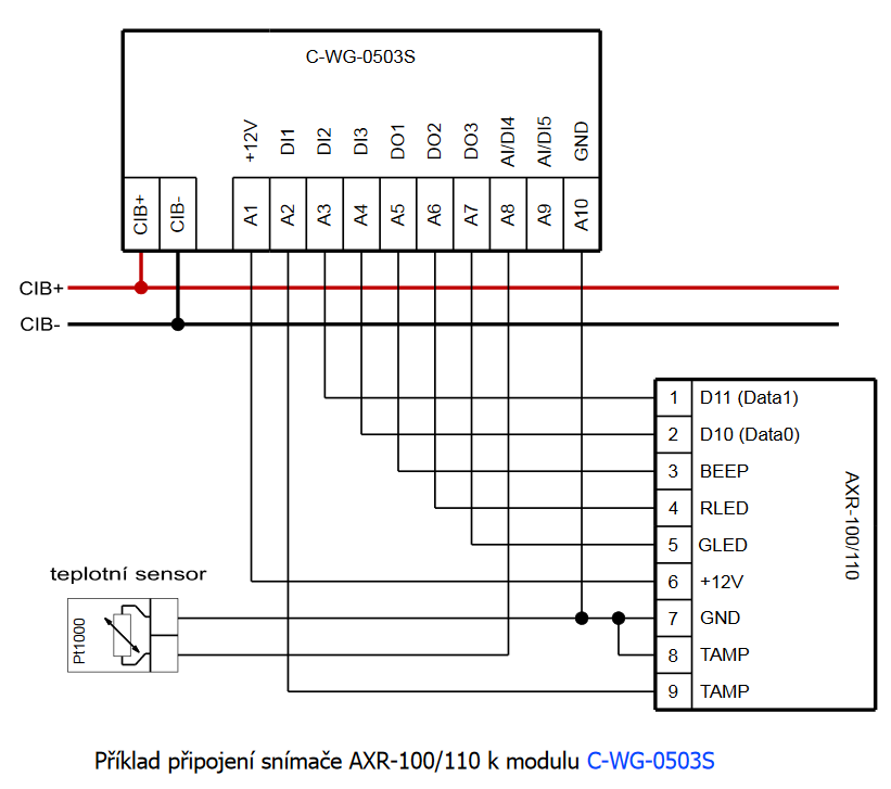
- Connecting the AXR-100/110 sensor to the C-WG-0503S module - ...3.56 MHz can be facilitated by the AXR-100/110 sensors (manufactured by EFG CZ s.r.o ), which should be connected to the C-WG-0503S module. The module provides powering the sensor, communication between the Wiegand and the sensor, and con...
- Connecting the SSA-R1000/1001 sensor to the C-WG-0503S module - ...rd readers SSA-R1000/R1100 (Samsung Format, 125 kHz) and SSA-R1001/R1101 (MIFARE, 13.56 MHz), produced by SAMSUNG, to the C-WG-0503S module is described in this chapter. The C-WG-0503S module provides communication of Wiegand with t...
- Connecting the SSA-R2000V keypad to the C-WG-0503S module - ...dentifiers) reader is best arranged by utilizing the SAMSUNG-produced SSA-R2000V keypad, which should be connected to the C-WG-0503S module. The sensor is equipped with a numeric proximity keypad and a proximity card reader in two variants: the...
- Connecting the ACM08E keypad to the C-WG-0503S module - ...with a proximity reader of cards or similar identifiers can utilize the ACM08E sensor with a keypad connected to the C-WG-0503S module. The sensor is equipped with a numeric contact keypad and a proximity card reader in accordance with the...
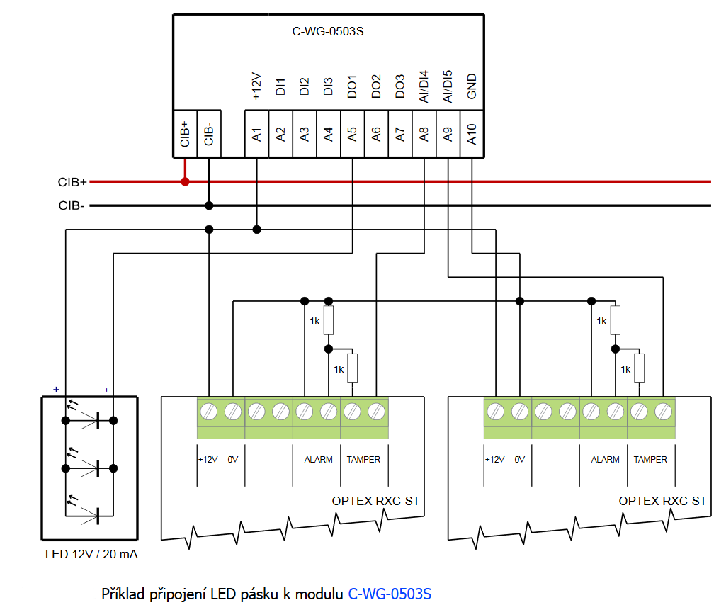
- Emergency lighting - LED strip with module C-WG-0503S - For easy-to-implement emergency lighting, we can use the C-WG-0503S , module, which will provide us with 12 VDC power supply and control (binary output) for LED strips, which can be fitted into a standard lamp. E.g. 5 cm of ordinary LED str...
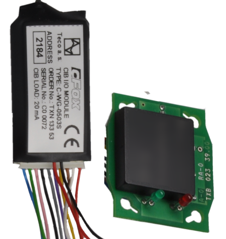
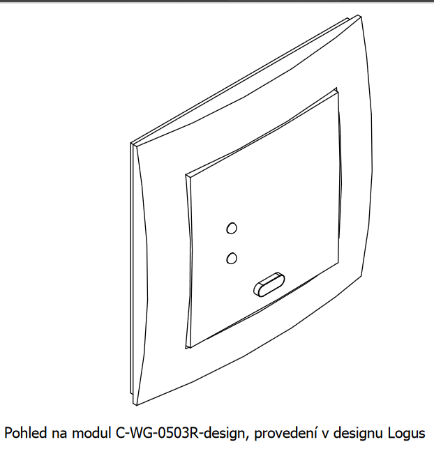
- The RFID CFox card reader in the interior design, the C-WG-0503R-design - ...e.g. for connecting temperature sensors or a PIR detector, etc. The detectors can be powered from the +12 V output of the C-WG-0503S module; a maximum of 25mA is available (a maximum consumption of the powered detectors). The readin...
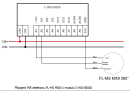
- Controlling lights using the PIR detector Vantage FL-MS - ...en collector output, so it can be easily connected to the inputs switched against signal ground, e.g. the DI1 to DI5 on the C-WG-0503S . The PIR detectors usually use NC outputs, but always with a relatively long switching time (from 500 ms to a...
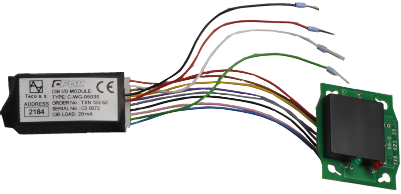
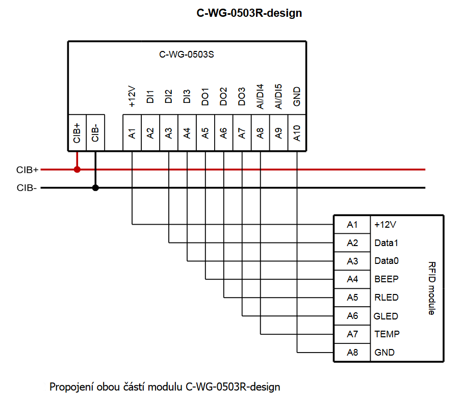
- The RFID card reader for a customized embedded design - ...ID module Notes: By default, both parts of the module (the RFID scanning part and the embedded C-WG-0503S part) are interconnected with separate approx. 100 mm long wires. The connection can be extended up to approx. 1...
- Contact-free identification, RFID sensors - ...ielded cable with a miniumum 0.35 mm 2 cross section. Sensors with the Wiegand protocol can be connected to the C-WG-0503S module or to the MX-0301 submodule....
- Emergency lighting in the house - ...d in standard lights as an additional source, e.g. a short LED strip powered from the 12 V output of CFox modules (e.g. the C-WG-0503S ) - see the following example ....
- Connecting a PIR detector with a double-balanced loop to C-IT-0200S module - ...ble, such as the C-IT-0200S module. Here you have to provide a 12 V power supply for the detectors, unlike with the C-WG-0503S module, which itself provides both 12 VDC and processing of two balanced loops, and can also be connected to a...
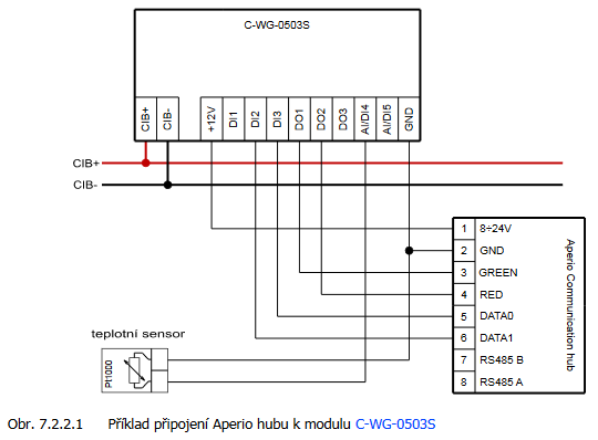
- Connecting the cylindrical insert with the integrated reader APERIO C100 - ...the wireless APERIO C100 cylinders or E100 escutcheons manufactured by Assa Abloy , there should be used the C-WG-0503S module with the Wiegand protocol. The Wiegand communication HUB should be connected to the C-WG-0503S m...
No data available.